Category Archives: Uncategorized

My Silly Pondcam Post 7 – Almost There

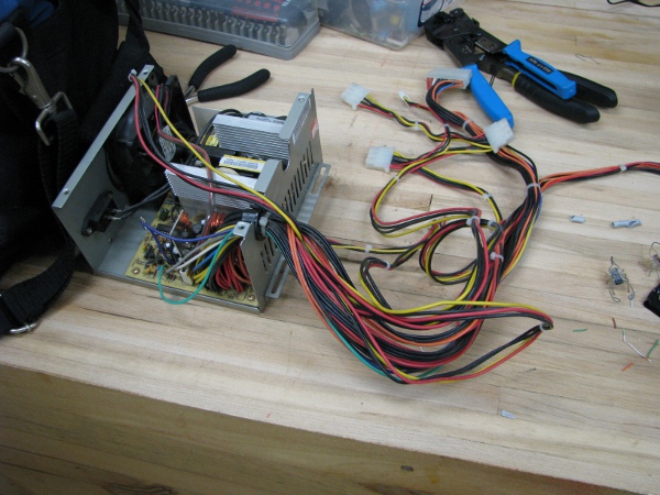
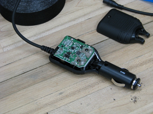
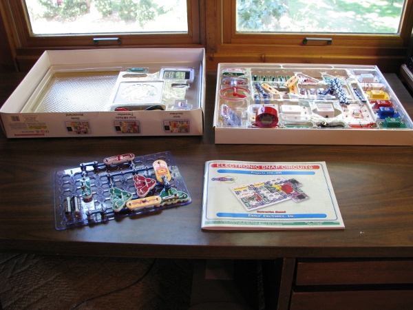
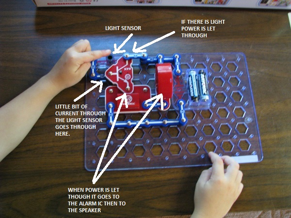
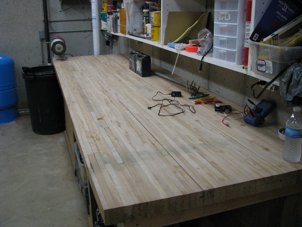
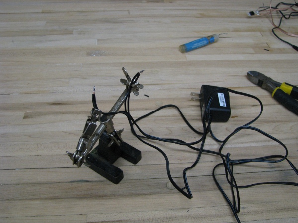
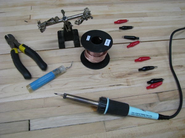
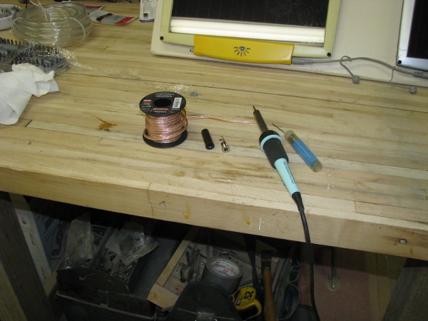
OK… Last thing we did was test our relay light and finally made sure the camera would run reliably on that 12 volt battery. I glued that photoresistor right to the front of our camera and that is dry now. We really need to test that. First I need some more wire. I really hate all the wire I am using. They are all very stiff. The problem is I don’t have any other wire, so I am stuck.. But I do have a lot of old power supplies from computers. Lets bust one of the broken ones open and steal some red and black wire.

pc-power-supply

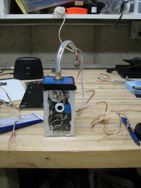
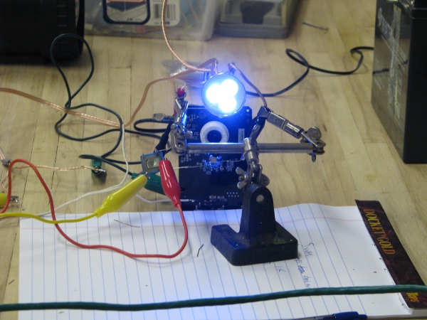
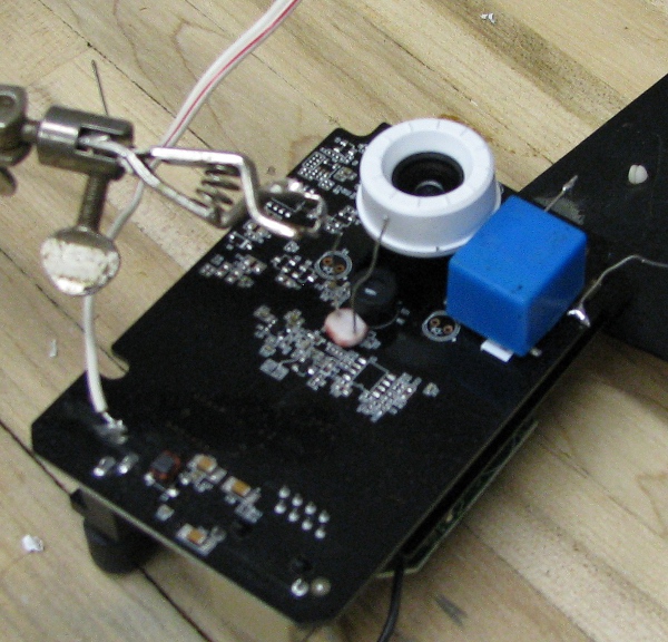
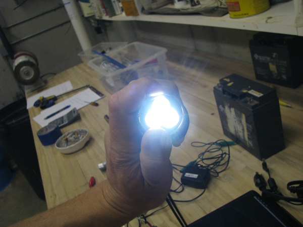
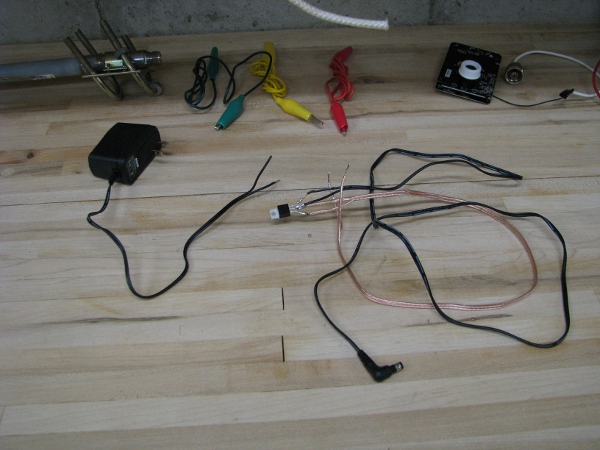
I solder everything up permanently. Connect the relay to the 12 volt power from our camera power supply, then I connect the light through the relay and pick 5 volts off the 5 volt power jack in the back. I position the light at the top the camera as it would appear in our water proof case. This is what it looks like.

camera-with-light-attached

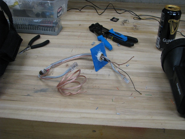
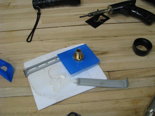
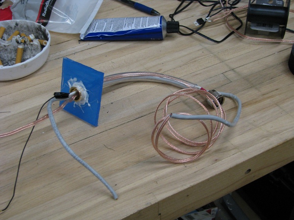
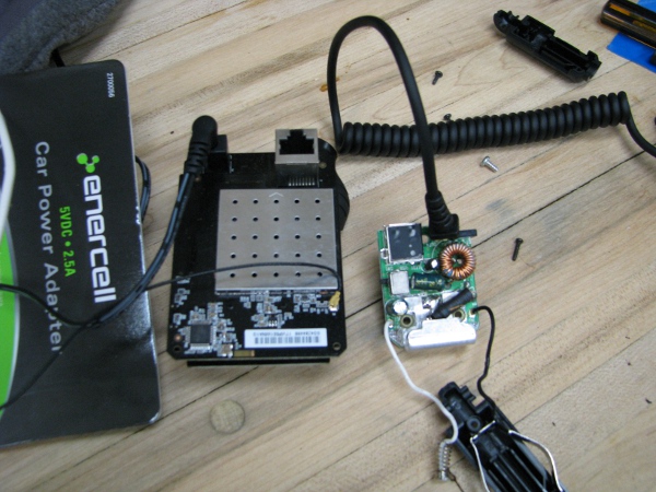
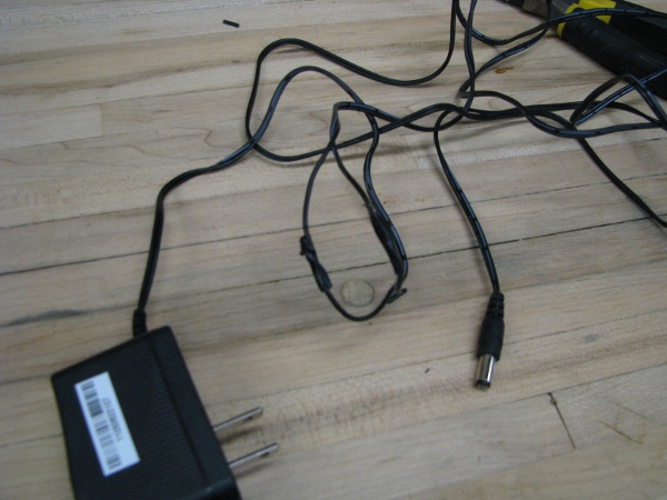
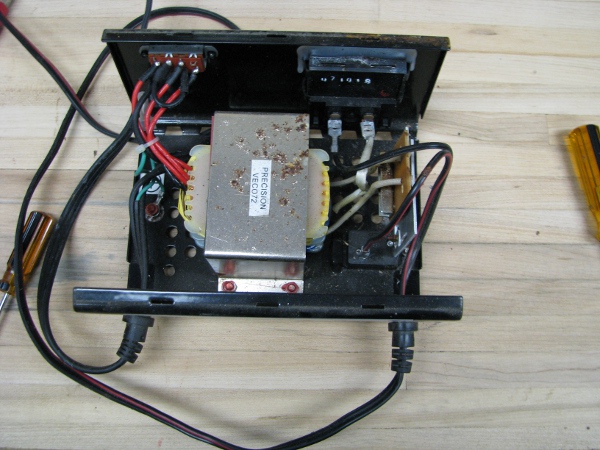
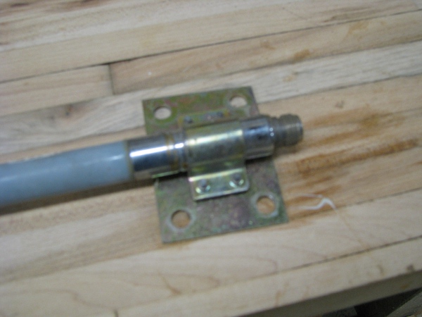
I now have to attach our top with our cable  assembly for power, transmission and network. I solder all the connections permanently.

attaching-cable-assembly

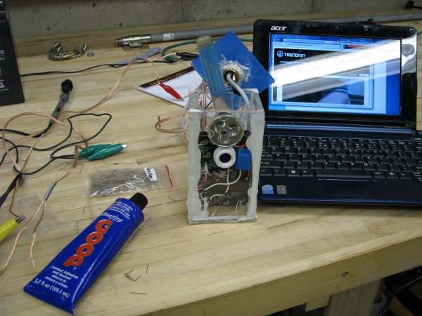
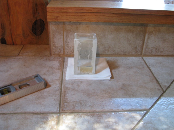
I slide it all into our case. It fits really nicely. A little snug, but that is good. I have trouble getting it in there because the wires are stiff and tend to spring back away from where I want them. Here is how it looks.

camera-in-case-test

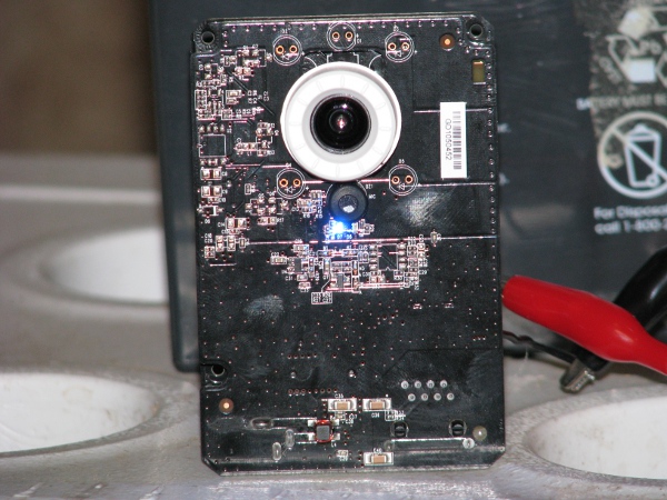
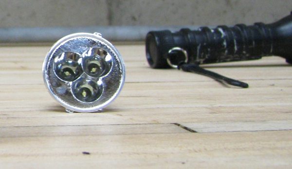
I can’t glue anything in place permanently now. I may have to take it all apart again as we have not tested our photoresistor that is glued face down on those LEDs in the front. As I tape the top on the light gets pushed off the plexiglass and now sits crooked. I make a mental note that I will have to spot glue that in place before putting the top on permanently. Here is the full camera without the antenna that we will be testing.

camera-top-taped

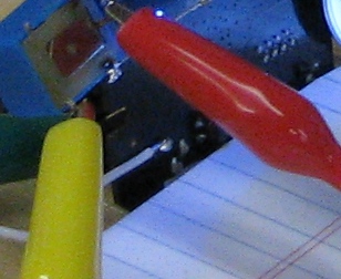
We are so close. At this point I really just expect everything to work. That photoresistor is right there up next to the LED, so we really should be good. I attach the camera to the power supply and watch it. Right away I see something that isn’t right…

power-up-camera-with-light

The little LEDs are on, but our light is not on. Then something happens. I can’t take a picture of it, so I will have to explain it. The network activity LED (The red one that flashes, is tripping the relay. Every time that thing turns on and off the light blinks. It is blinking and blinking and I can hear the relay going off like a telegraph machine from the movies and with the light it is like a disco. It is kind of cool looking, but useless as we cant have it be that way.

I can see right away there are two things wrong. First I connected the light to the wrong leg of the relay. One of the legs is a closed switch when the relay is not active, the other is closed when the relay is active. I move that first and test. It is still almost the exact same behavior where the flickering LED is controlling the light instead of the steady LED right next to it.

I need to fix this. We are way too close. There has got to be a solution. In my mind I am thinking it may be a long time before we get this back into the case as this just doesn’t seem right at all. I may have to go back to transistors.

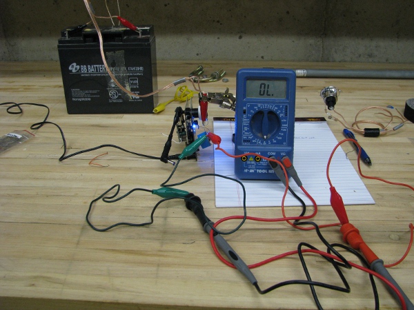
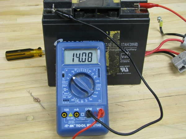
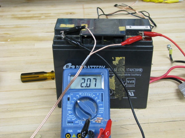
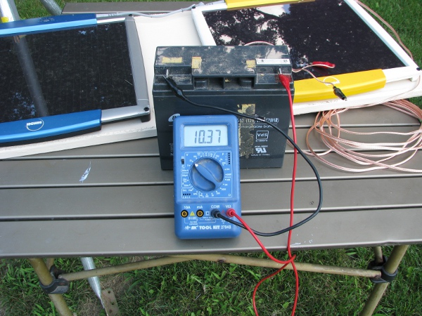
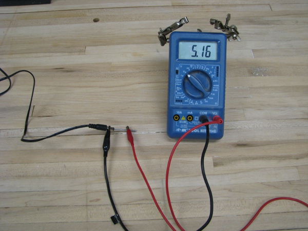
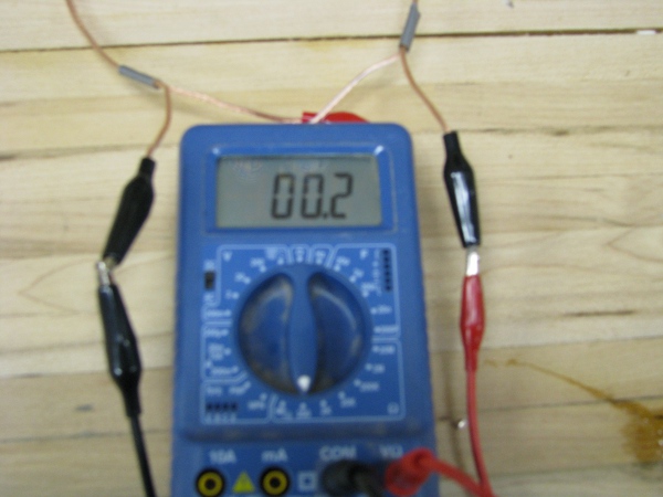
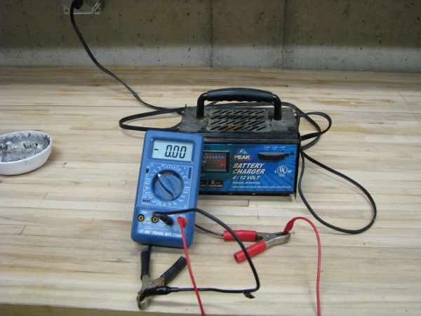
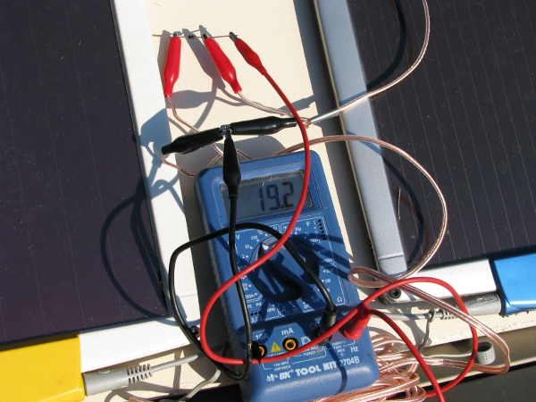
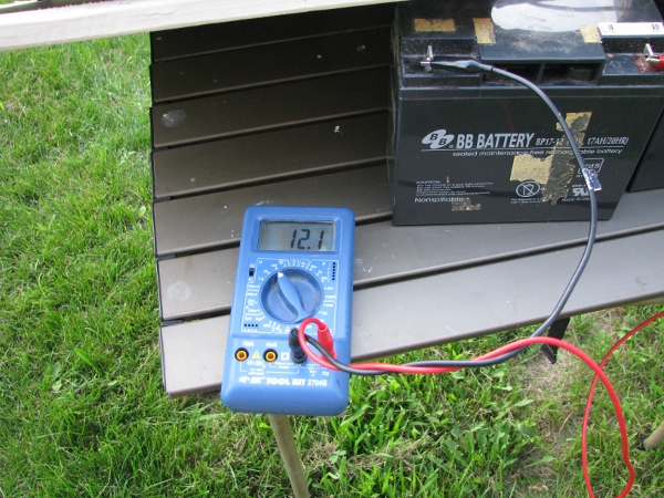
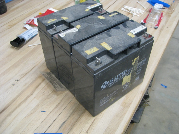
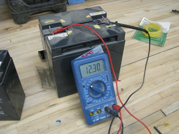
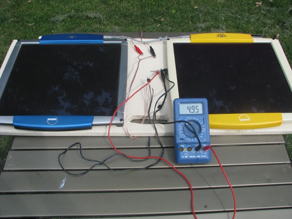
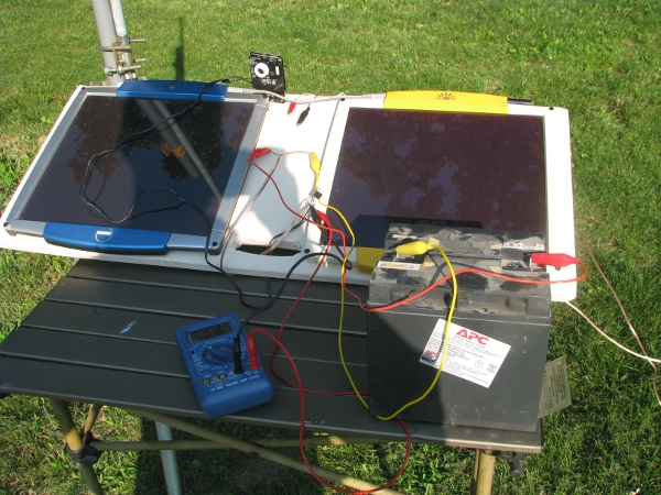
I don’t know if you have every had this feeling, I have it all of the time. When I run into problems, almost no matter how complicated, I always have this feeling like the solution is right their for me to know and I just have to find it from somewhere in my brain, it is like the solution is right there and I can get it. I have to think about this. The solution should be simple. I know we need more current and I want to pick that extra current up by the light. I remember our batteries weren’t very good at the beginning of this project and grab a voltmeter to measure the voltage from our 12 volt battery. Nope… 12.7 volts. That is not the problem.

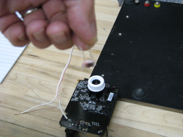
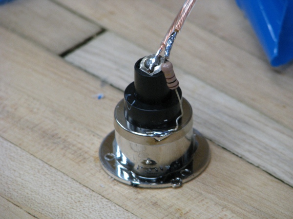
I can see a little blue light coming from through the glue so I decide to put another photoresistor and glue it face down right on the blue that I see coming through the bottom of that one photoresistor that is already glued down. I temporarily wrap the ends around so it is in parallel to the original. As it detects a little light, it should just dump that little extra current to the relay to make it behave. It will be a little ugly, but our camera is already very ugly. Here is what it looks like as I glue it in place.

dual-photoresistors

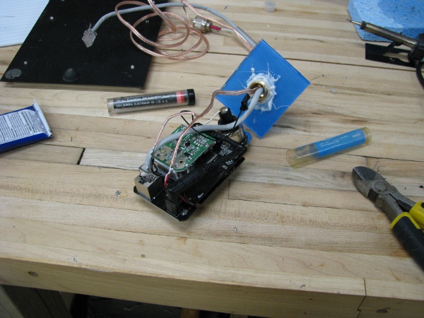
Here is a better shot of what it looks like from a different angle after it is dried.

two-photo-resistors-in-parrellel

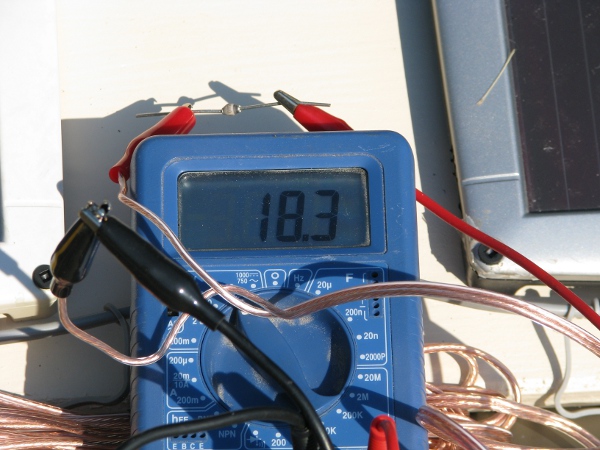
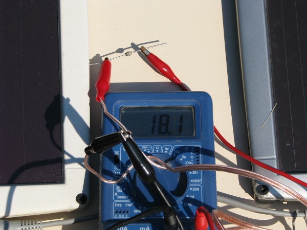
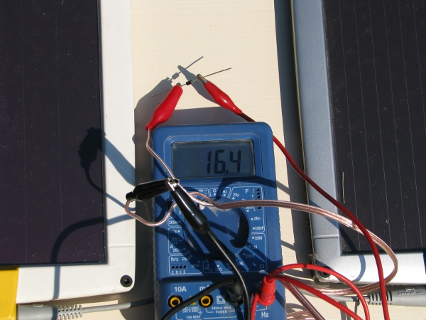
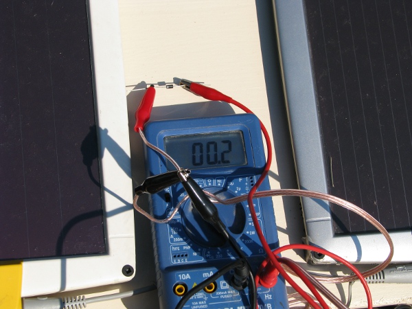
I test it and it is still exactly the same. That didn’t help at  all. I need to add more current. I think, “who says we have to use a photoresistor for getting that extra current?” I will just add a resistor right across. It may cost us a little more power even when we are not using the light, but it should be a small amount. The added bonus of this is I get to do math to get me close (I don’t know anything about those photoresistors as there was no documentation with them so it was just trial and error all the way).

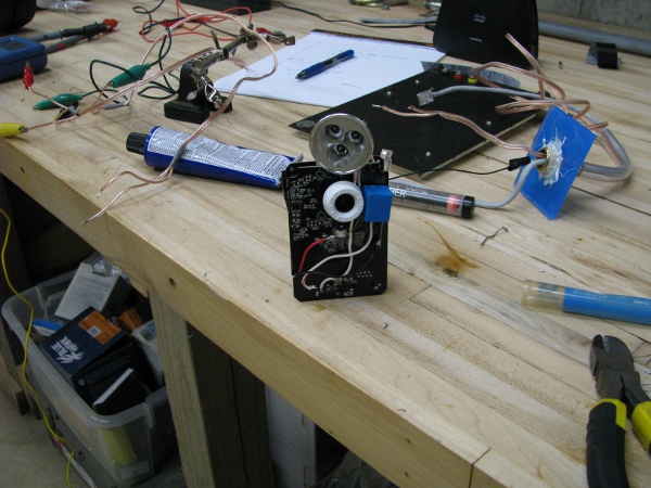
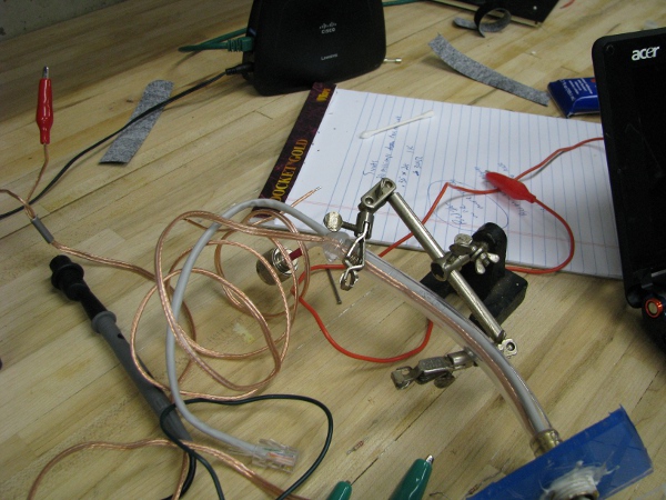
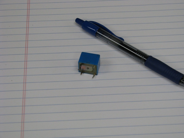
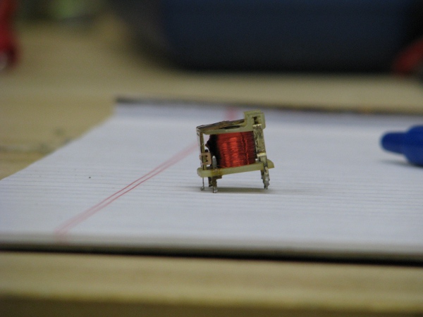
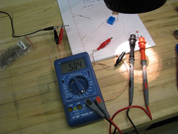
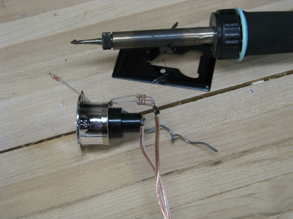
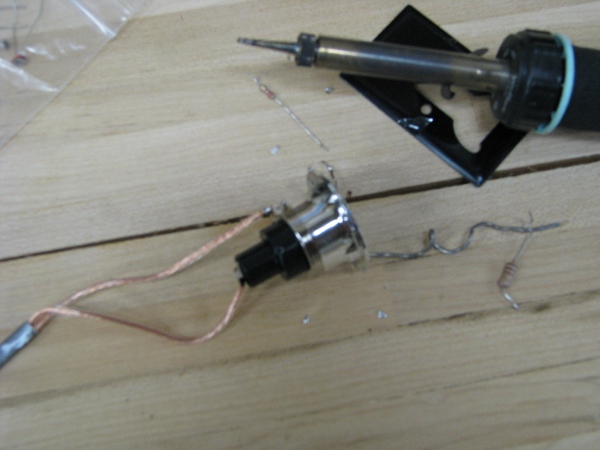
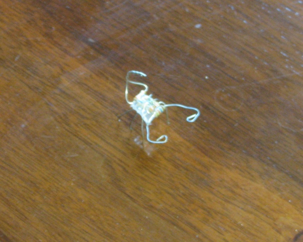
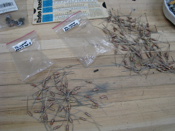
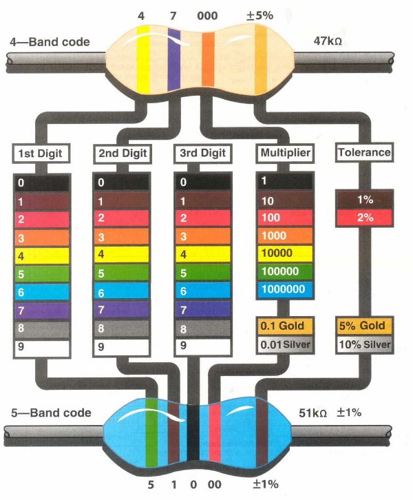
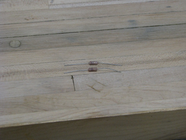
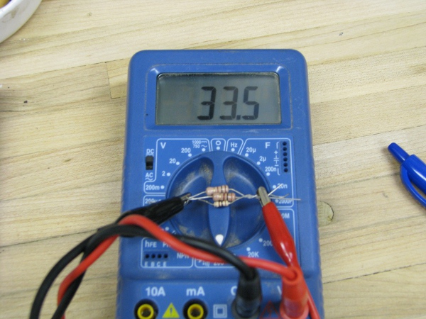
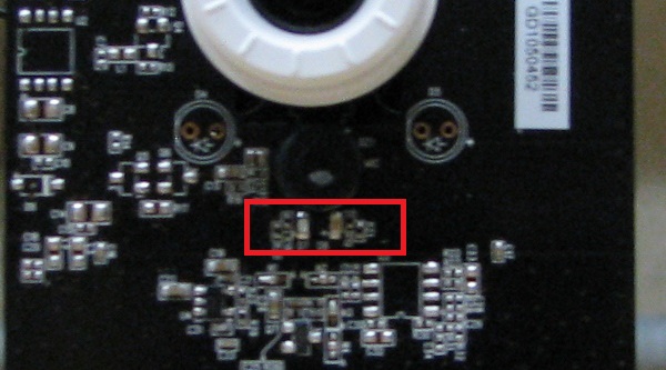
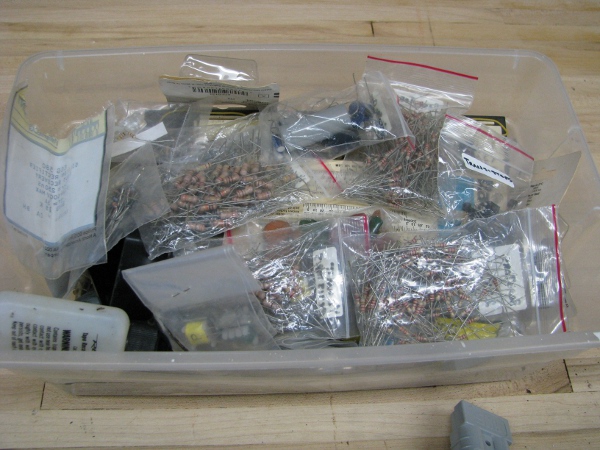
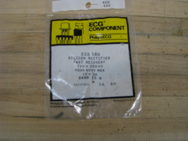
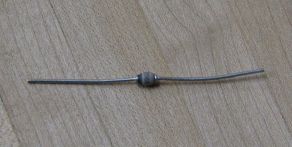
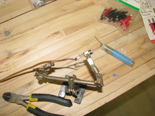
We took a lot of measurements with our ampmeter to understand how much power was required for different parts of this circuit. If I recall correctly we wanted to get 250 ohms from 5 volts to drive that relay shut. We are now using 12 volts, so that would bring us around 580 ohms or so to make it turn on the light. I just take a simple guess that if I put a 1000 ohm resistor in there, it just may do the trick. It may just tune the circuit to the output brightness of the blue power LED on the face of the camera. I look around through our resistors and really am in no mood to mess with the color coding because we already covered it and I am bored with it. Then I see this.

1k-resistors

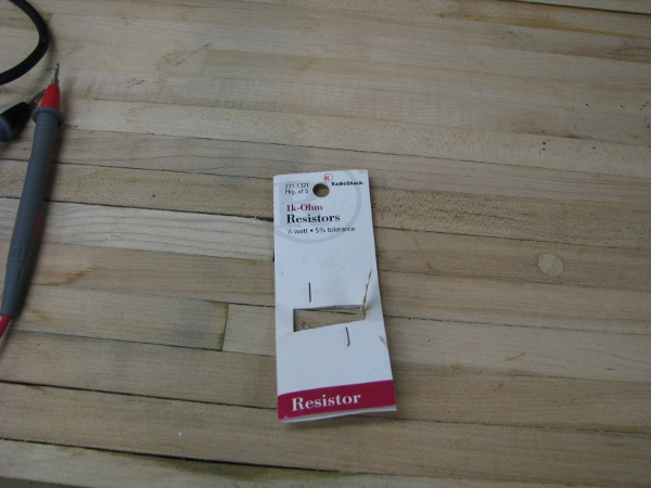
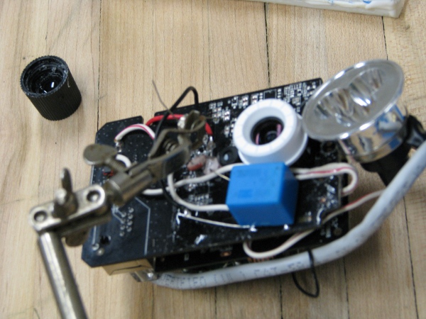
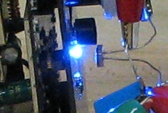
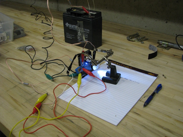
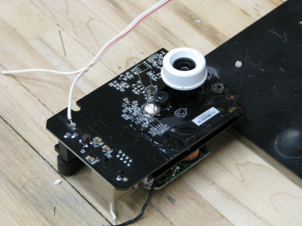
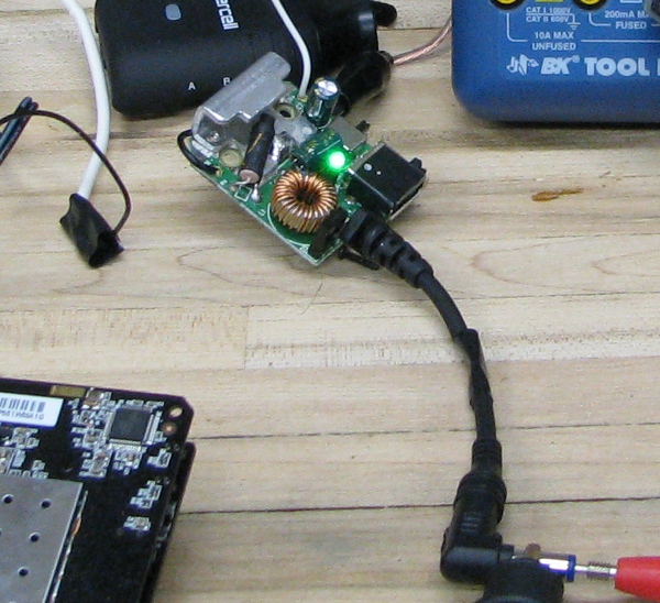
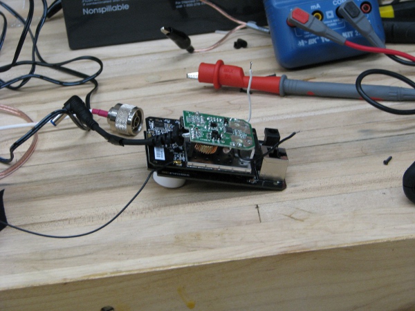
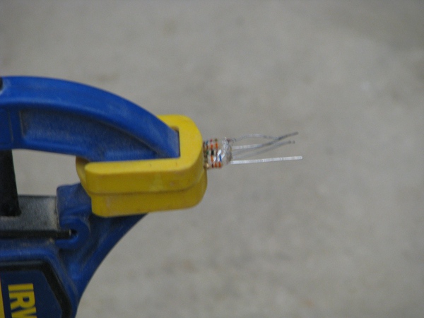
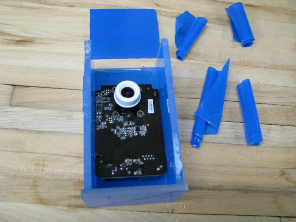
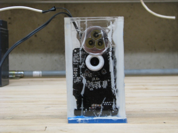
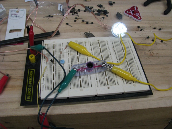
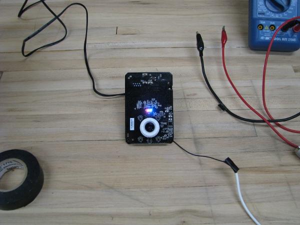
There were two left in that package, I used the other one for our circuit. I test it and now the light stops oscillating and just stays on, even when the little activity light is flashing. This looks really good. Here is a picture of what those three components look like all soldered together in series and glued to the face of the camera (I tell ya this camera won’t be winning any beauty contests, I think I will call it “frankencam” instead of “pondcam”). Notice the light is on and stays on.

resistor-and-pr-in-parallel

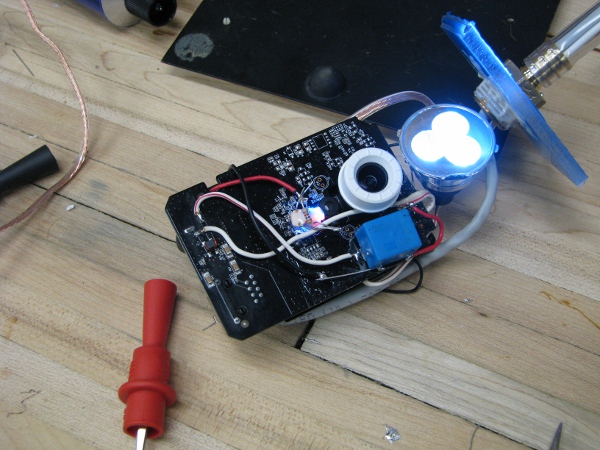
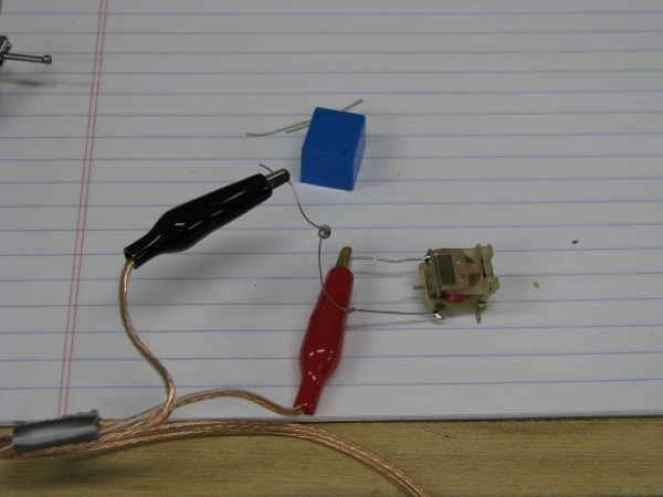
If you look closely, we have two photoresistors and a 1K resister right between them. Now I have to test this to see if it all works correctly. I need to turn that light off with the software of the camera.

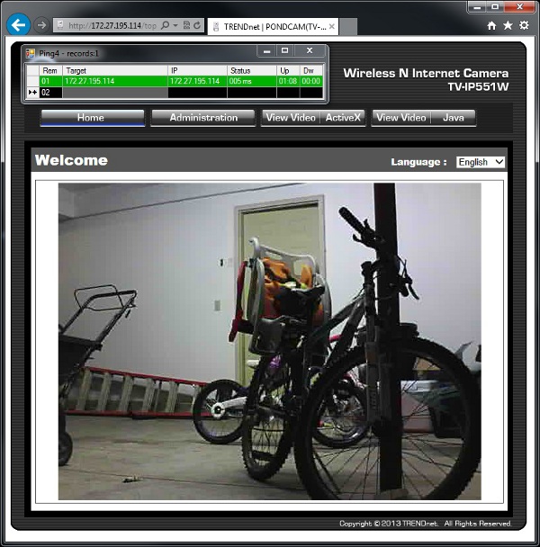
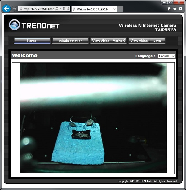
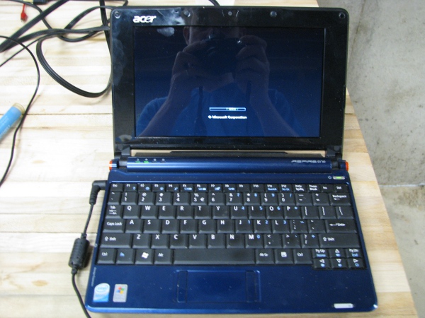
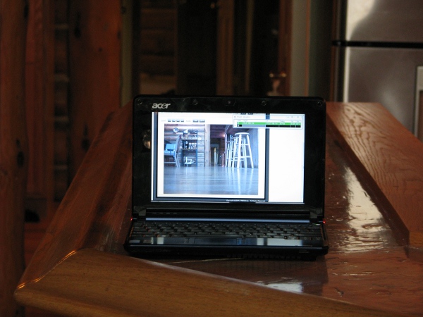
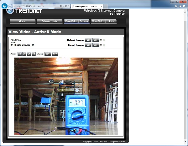
I grab the netbook and connect it up to the camera. Yes… It still works.

Note: When I first booted the camera up I could see it on the network and login to it but it didn’t show me an interface view that you have seen many screen shots of so far. I was so scared I accidentally shorted something out. I didn’t take a picture of it because I thought it was all over for the camera. Fortunately I noticed that as we were moving it in and out of that case, the two boards that comprise the camera were getting separated (they are connected together by nicely placed board connections that hold them together). I pushed them back together and it worked (I was totally relieved).

camera-works-with-light-on

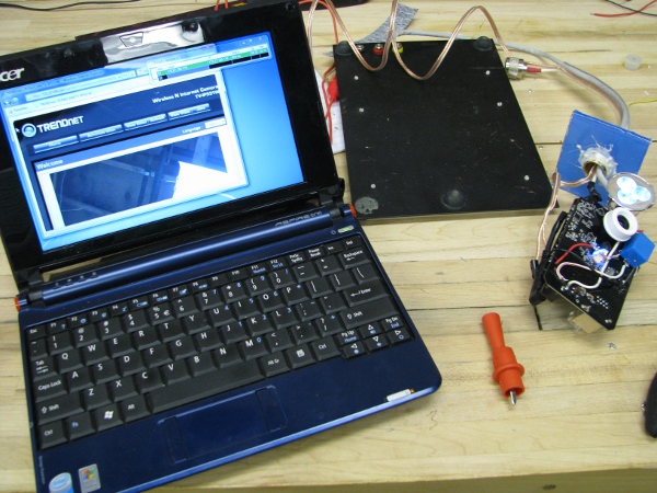
You can see from the above picture three important things: 1) The camera is working and correctly showing what it is pointing at; my workshop ceiling on the computer. 2) The camera light is on. 3) The little LEDs are on too. Now all we have to do is turn them off in the software and see if that drops the current to our relay and turns off the light.

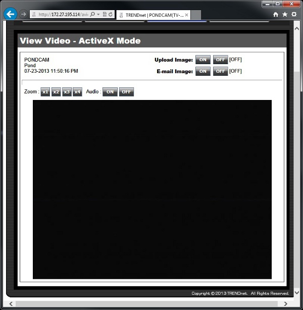
This is a picture of me turning off the LED in the software (The picture is really crappy and you can hardly see it so I put an arrow in there).

led-control-light-off

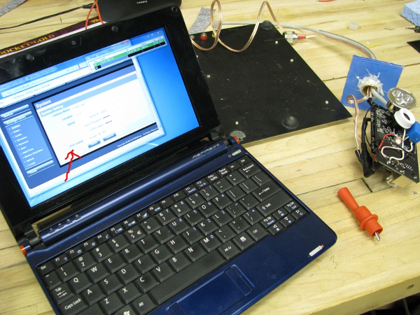
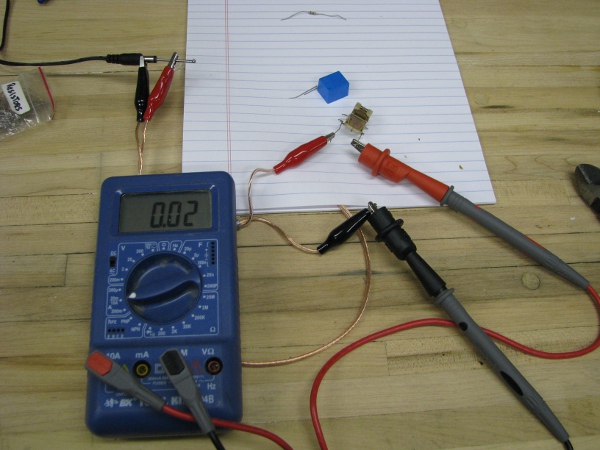
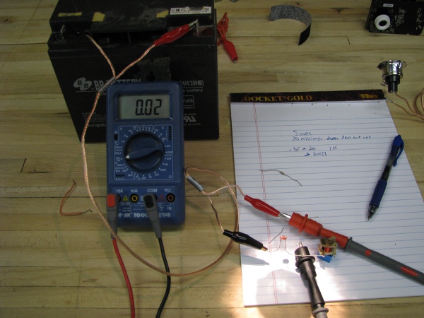
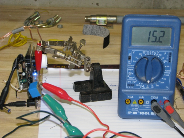
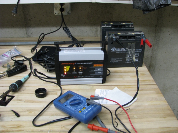
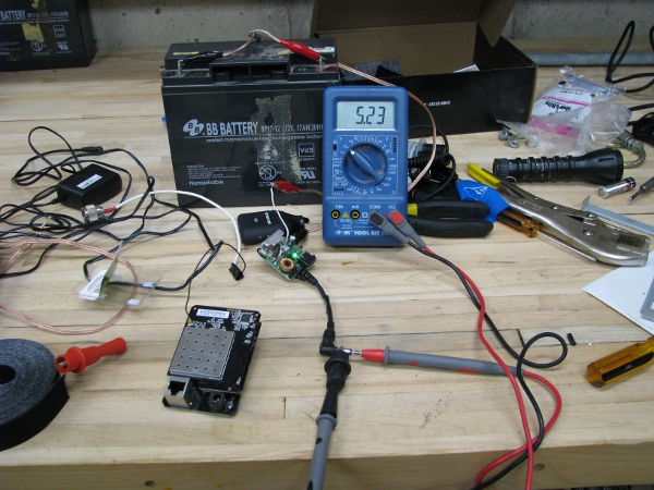
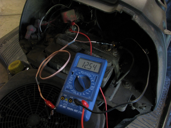
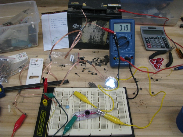
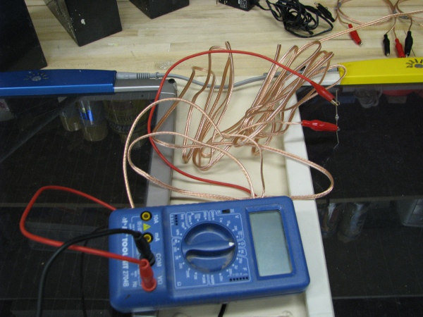
So… I turned off the light with the software (notice the light is, in fact, OFF!). I am so excited, we are ready to put this thing together again. One more test though, I want to see how much power that light/relay assembly costs us from the 12 volt battery. I connect my ampmeter with the light off.

full-camera-light-off-amps

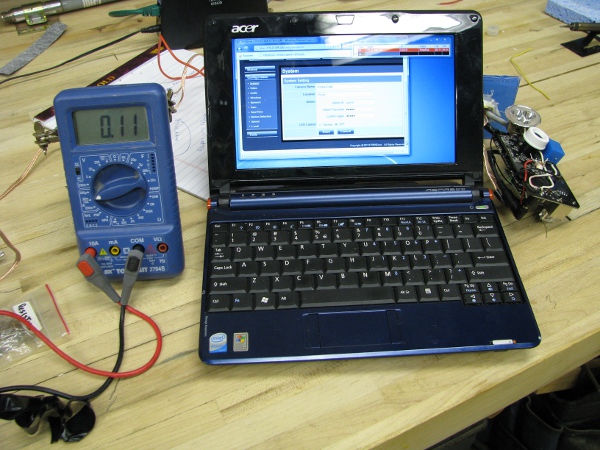
110 milliamps???!?!?! Is that all. I am feeling so good about this thing right now. How about when the light is on?

full-camera-light-on-amps

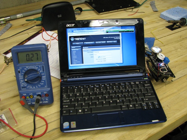
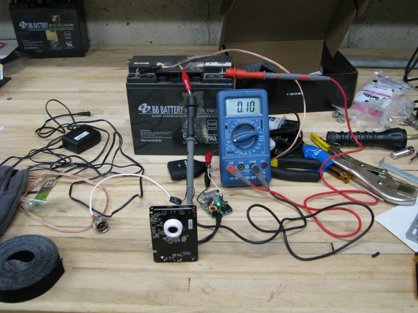
Gadzooks! 270 milliamps. Wow! That probably wasn’t the best way to turn on that light. Just to have that on more than doubles our camera power consumption. I don’t care though. I just have to remember to turn the light off when I am done looking at it. I wouldn’t want to leave that on all of the time anyway.

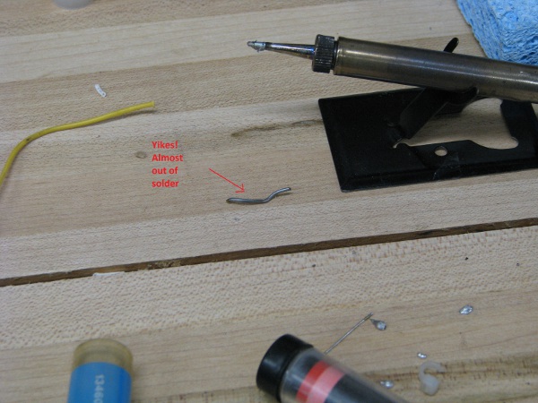
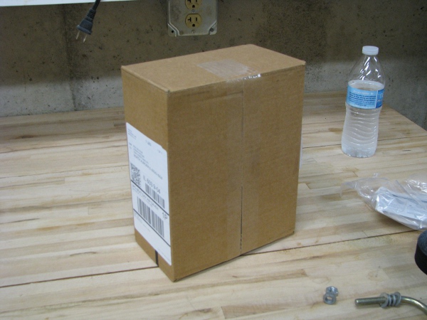
I think we are ready to put this all back together and the time for soldering/math and other complicated things that are hard to follow are OVER (At least I hope they are). One thing for sure is this. I am almost out of solder.

no-more-solder

Let’s get this sucker back into the case.

full-camera-in-housing

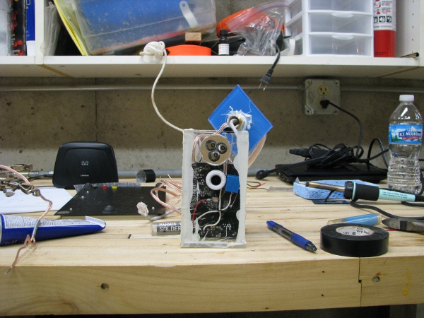
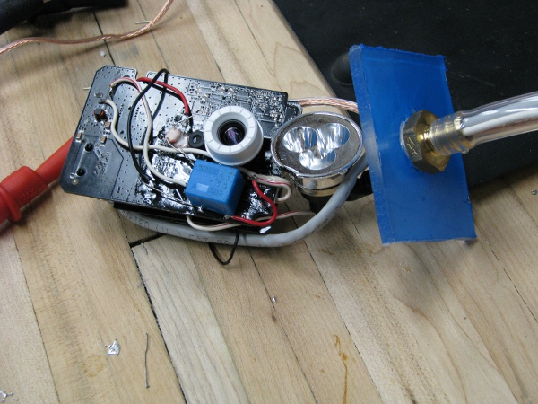
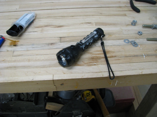
Oh… That is nice. I want to permanently position that light so it doesn’t move though. I put three little dabs of Goop on the top and two sides of the face of the light, then hold it where I want it by using one of our empty solder containers to push the thing into the plexiglass. Here is a picture.

gluing-light-to-housing

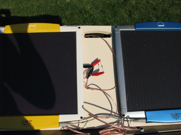
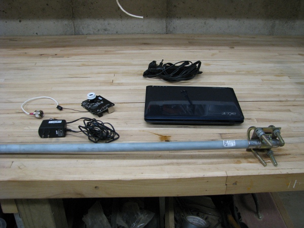
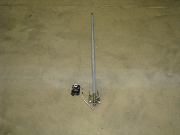
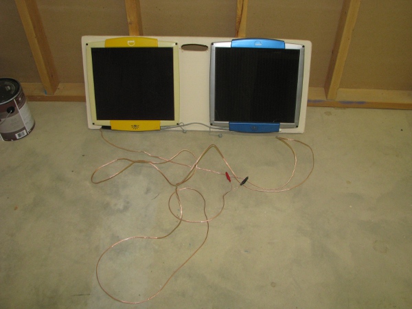
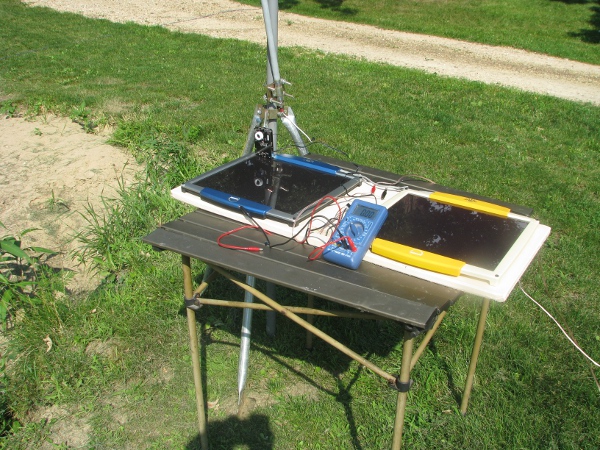
OK… That has to dry so I can’t do squat with it. I have to think of something to do to move this project toward its intended result. I have been asking myself a question for a while. And it is this. How am I going to keep this camera under water? If I stick this in water and it is water tight like I want it, it is gonna float! I thought about weights on the bottom of the camera, but scraped that idea before I got even close to attaching one. Let’s bring our antenna mount in from outside.

antenna-mount

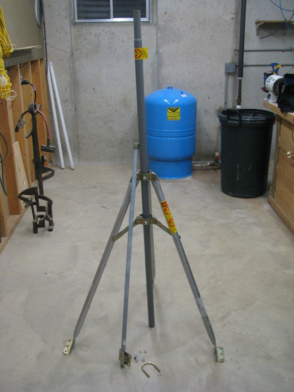
I like this thing. It used to be on my old house. I got that 10db antenna because I was planning on seeing how far I could get wireless to go across town from my old house (I used to do some work for a wireless Internet provider, I got an antenna like this to go for over a mile).  My plan is to use these brackets to mount the antenna to the center pole and have our camera fastened to the bottom. Totally easy solution.

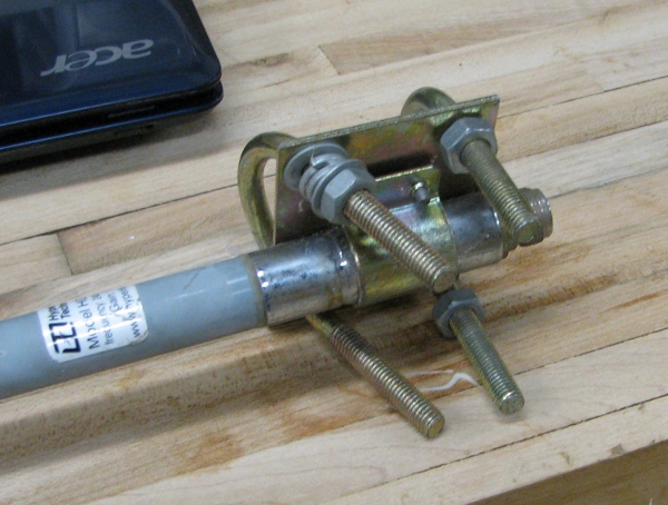
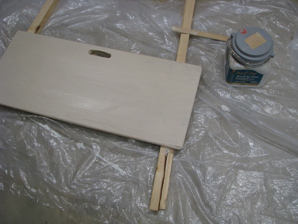
I cut a chunk of wood from a 2×4 and drill some holes in it to offset the antenna so it will clear those bolts that are used to secure the center pole. This is not what this mounting system is designed to do at all, but I can see right away it will work just fine. Here is where we are after I drill a few holes and put it together.

antenna-on-roof-mount

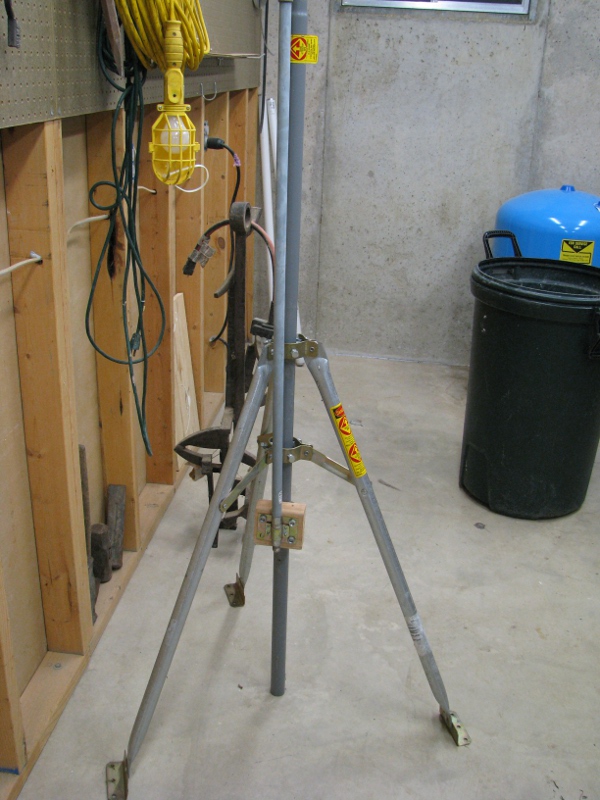
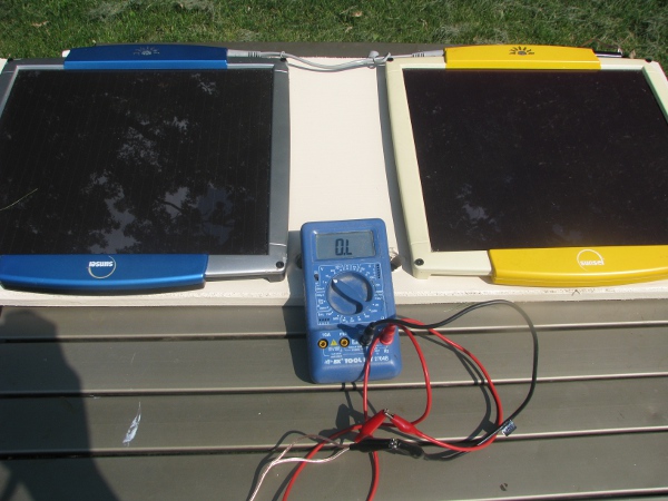
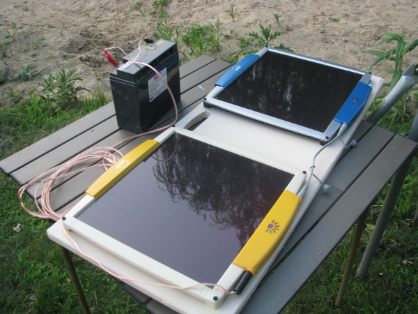
This is perfect, when we are ready, I will attach our antenna to the camera and then run our 12 volt power cables to our solar panel / battery power source. The plan is for the pondcam to be at the bottom, securely fastened to that pole under the antenna somewhere.

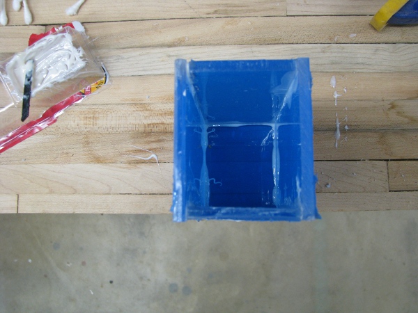
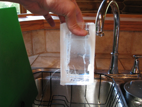
OK.. What now? I am waiting for glue to dry so I have to think of something to do. Oh… I know… Since everything is coming together so nicely, I have to worry more about our water proofing. The top of our cabling harness needs some glue, let’s squish as much glue as possible into the top of the harness (Remember the harness is going to be facing up. Rain will hit the antenna flow down right across that thing. If we don’t totally waterproof that, it will leak right into our camera from the cable assembly. That would be BAD NEWS! as it will flow right down right on top of our camera). Here is a picture of where I leave it overnight. If you need an idea of where to focus, there is a total mess of glue on the top of that tube that holds all of those wires.

gluing-top-of-of-wire-assembly

It is the next day and all of that glue should be dry. I am thinking we really need to get this in the case. It is for several reasons:

1) It moves us closer to our goal of getting it into the water.
2) That camera is more fragile than just the boards and the camera that it mounted on them. They are plugged together and they easily come apart when I move it around which causes problems. And all of the wires, relay and light that are soldered to it; it is just one wrong move with having some wire touch the wrong thing and then bloop! dead camera.
3) Glue takes a long time to dry. I need to use glue to make it water proof. So I better get to gluing because this has got to get in the water ASAP.

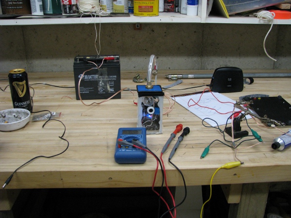
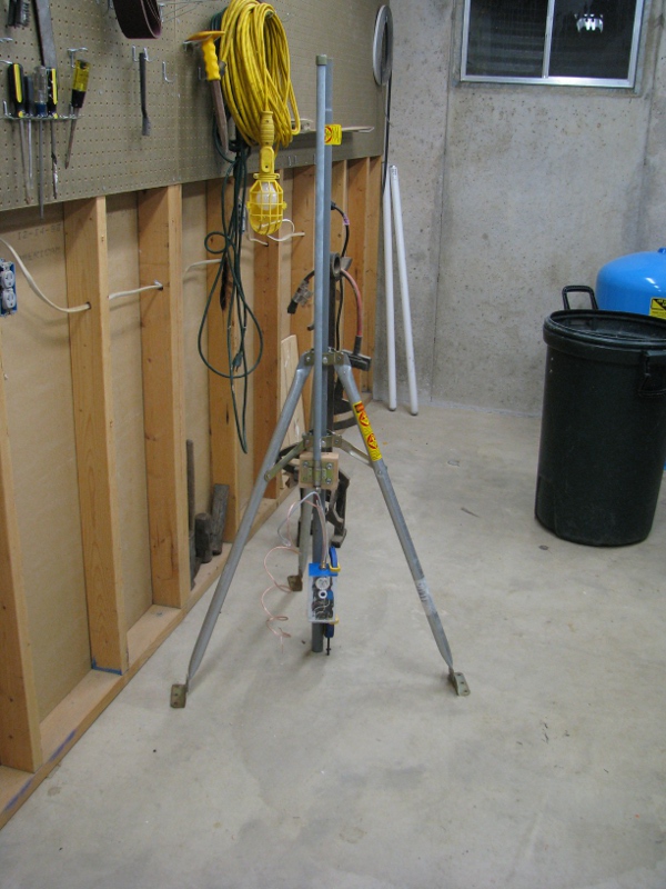
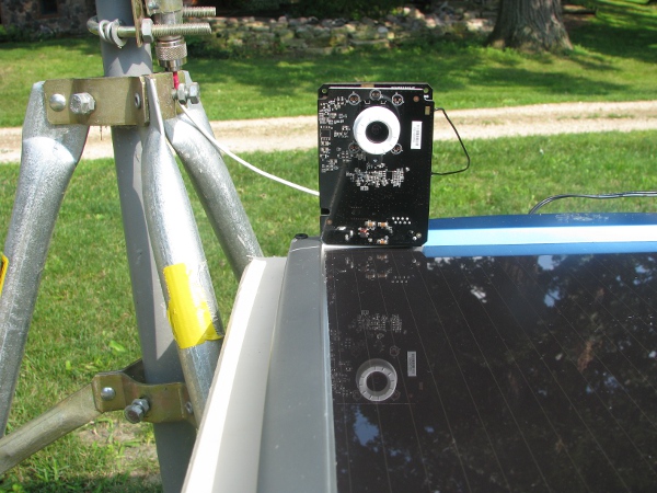
We need to test our camera again, but in the case without gluing it. Why? I need to know if that antenna still works. I have pulled that little plug and messed with wires and moved it around. I need to make sure the connection to our huge antenna is working before putting that top on. Remember the connection to the antenna? I made that a couple of weeks ago during post 1. With all of the stuff we have done we could have totally compromised that connection for the antenna.

So I place the top on and clamp it down with a C clamp (There is a more modern word for this type of clamp I am sure, but I will call it a C clamp for now). And then I connect it to our antenna under the roof mount.  Here is what it looks like.

1camera-on-mount

It fits really nicely. Imagine that thing just plopped into water. The camera itself will be about a foot down. Out of the top will be our 12volt power wire. I am hoping putting this thing in the water is just really easy with this. I imagine just walking out to the pond, finding a decent home for it. Then plopping it into the water and attaching the solar panel / batter power assembly. I really hope it is that easy. I will be very disappointed if it doesn’t work out that way.

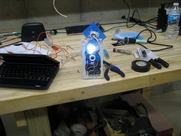
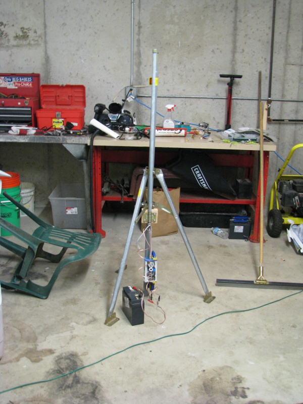
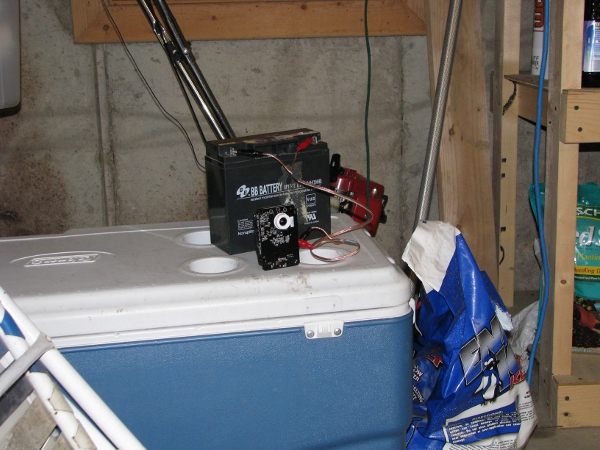
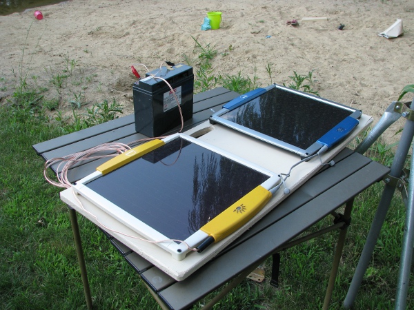
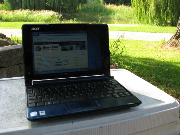
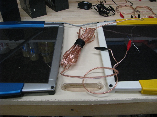
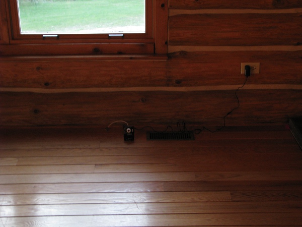
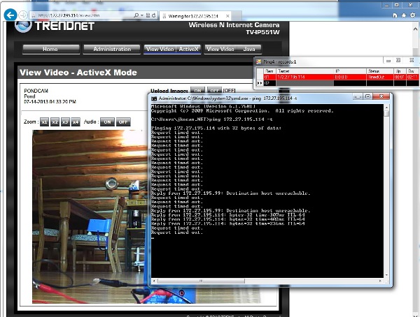
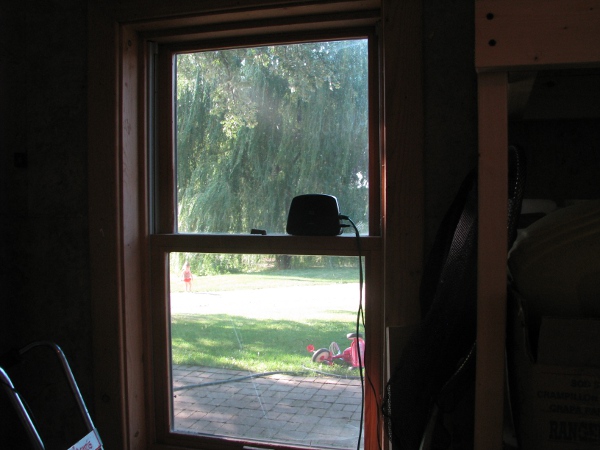
Next I grab the battery and some jumpers and bring it out the garage. Remember to test if that antenna is working I have to bring it as far away from it as makes sense (The garage is about 40 feet away and I am sure to close the door to the garage before testing). Here is what it looks like in the garage.

1camera-in-garage

I look at that picture and I imagine it 1ft under water. Just looking for fish. I hurry up and power up the netbook to check it.

1camera-on-in-garage

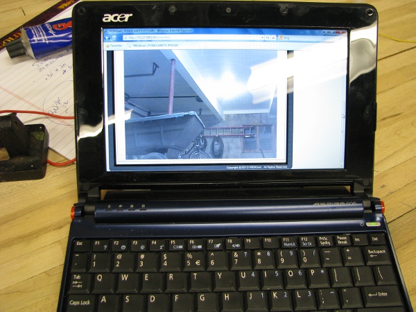
Yep… That is what I was expecting. I know what you are thinking, “Does the ‘Tim Light’ still work”? Let’s see. I go and turn off the garage lights. Then turn on the camera light in the software.

1tim-light-works

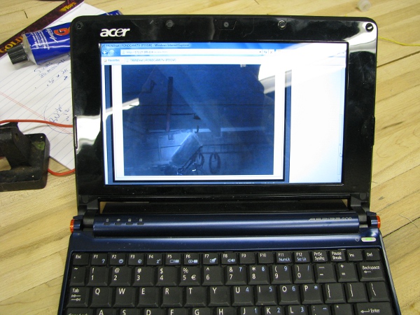
It was pitch black in that garage when I turned off the lights. I did check it with the camera to see if it could see anything. That little light is very bright. I can totally make out the back of the wagon and even the water hoses on the back wall. This should be able to see fish a few feet away from the face of the camera, even at night.

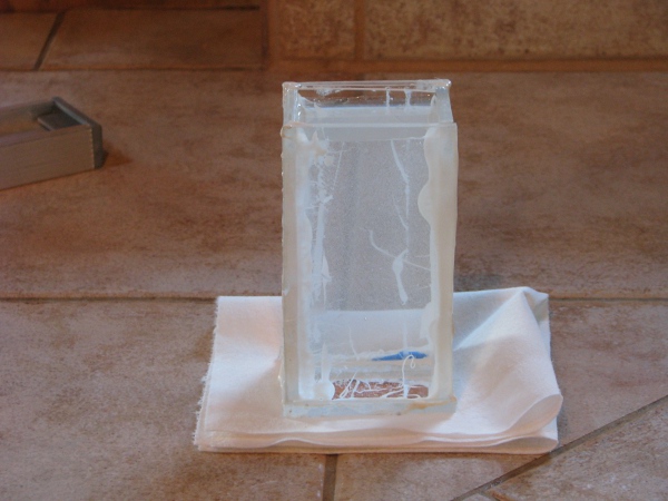
I am totally satisfied with all of these tests. Let’s seal up the camera and let it dry overnight. I add as much Goop as I can to the sides of the top of the camera. Remember how that water leaked after I epoxied the case together? I have to make sure this is really water proof. As I am writing this I almost want to put a water sensor at the bottom of this box to warn me, but that would add another two posts and I really need to finish this (Oh.. Just off the top of my head I can think of ways to have this project take an entire year). When I am done, I clamp it down with some C clamps and flip it upside-down so any extra glue would crawl across the camera overnight and instead will just land on the paper underneath.

1camera-drying

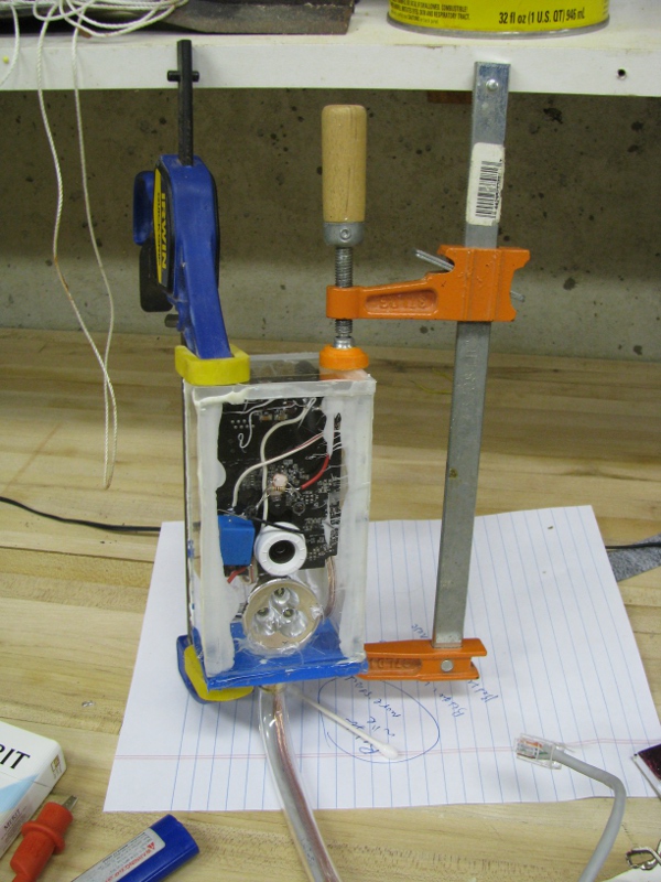
An hour later I go back to check on how it is drying. I am in a totally hurry and want to put this in the pond tomorrow. It looks dry enough for me to I start smearing Goop along all of the edges where glue/epoxy is to make sure it is sealed really well. While I was doing this, the top slid right off the camera and glue started to get in places where I didn’t want them. I quickly put the clamps back on and continued sealing the edges. When this happened the light popped off of its spot glue and is now a little bit crooked. This sucks, but I really want to leave it this way so I can sink it tomorrow. The light was pretty bright, it may be OK.

One last thing. I really don’t like the way that Ethernet cable end looks in this picture. If that gets into the water while the camera is on I am not sure what will happen. I have been thinking a lot about how to protect that from water today because this camera will be sunk tomorrow. I decide to clip the plug and spread some Goop all over the exposed wire. I can put a new end on in a few minutes so it isn’t a big deal. I would take a picture of this, but it is too hard. I am really tired and need to get some sleep.

To continue reading see post 8.

My Silly Pondcam – Part 6 – Light?

It is really late. I worked all day and wanted at least to start another post. When I started this project I had the outline of how everything would work in my head. Once I realized I had pretty much everything I needed to pull it off, I went nuts and just started building and posting. I thought it would take 3 posts, now we are on post 6 and we are not done.

I do a lot of complicated projects for a living, but this has taken all sorts of twists and turns that I wasn’t expecting. For example, I really wanted that “resistor bug” to scare someone. It was pretty strange and scary looking. It  should have grossed out someone, but when I showed it to my six year old she liked it. It looked just like a toy to her. Then I showed it to my two year old (that totally gets freaked out by any bug) and got the camera all ready to take a picture, I got this.

resisstor-bug-being-held

OK… Well that backfired big time. When they saw it they weren’t grossed out at all. They thought they were toys instantly and now I am building “resistor bug dads”, “resistor bug kids”, “resistor bug nests”. It is a whole production. I won’t have any resistors left when they are done (I had trouble making the resistors kids, I have to add “diodes” to my shopping list if I ever want to use one of those again).

I totally forgot where we were with this project as usual. Life has a way of having you lose your place in where you were with your amusements. So I have too look back at what we did in post 5 quick to get my bearings. OK.. I remember now… We got our waterproof case all set up. And our water resistant top too. We are on our way with that part.

Here is a picture of the waterproof case that has had water in it for a few days.

water-proof-case

It is totally holding water. It looks OK to me.

I had a family party the other day and I showed my mom the case that I tested in water. She noticed some issues with our epoxy on the case. It looked like it was breaking down on the inside a little or at least not holding well. She didn’t want to “burst my bubble”, but when someone brings up something like that, you have to listen. If you are working on a project and you are lucky enough to have some intelligent commentary, it is better to act than to just leave it. I need to worry more about water getting into my camera housing.

The other thing we figured out, or at least it looks like we figured out is power. My gut tells me we are OK there. It just seems like that little “car-phone-charger” was too perfect. So today I want to totally focus on that light. Yes… The light… Tim has such a great idea and we need to get that working.

As usual there is a real lot going on so I clean everything up so I know what I have to deal with. Everything gets put away except for the things I need to work on, all tools, etc. I am left with this. A desk that is as clean as I can make it.

workbench-clean-post-6

I will check our one “known to be good” battery fist.

charged-battery-full

That little green light to the left means that guy has a full charge. That is good. I really want to start using the battery as much as possible because we eventually need to bring the camera out to the pond. I think the battery will be charged by the sun, but have to go it alone all dusk, night and dawn before the sun starts recharging it. We need to know more about how this guy behaves in our actual circuit. We will learn that by using it.

Another thing I want to mention about our project and power is that we really should protect our gear from overvoltage or sending too much current. To protect sensitive devices it would be best to use a fuse. I know you are thinking, “Where is he going to get a fuse for this where he doesn’t have to use math to bore the heck out of me?”. Worry not… We have one already, we got this from our 12/24 volt step down DC transformer (previously known as our “car phone battery charger”), which now is our camera’s “power supply”. Wow… Our “lingo” is all messed up for that thing. Oh well better to have more than one thing to label something than nothing at all.

fuse-out-of-phone-charger

I don’t even have to learn anything about that fuse, because why? It was used in the specifications set on the package of the “car cell phone charger”. I am sure some guy with a higher degree than mine did a whole bunch of math to figure it out so I don’t have to worry. Everything about that package tells us we are safe to use it, so I don’t bother with any tests on it.

We have something to power the camera and at least we are close on the water proof (Until we really figure out a way to test it) and what I want to really focus on are all things we need to put in the water proof case. Power is figured out (I think), the connectivity is figure out (I think), the last thing is our 24×7 pondcam light. Let’s work on that.

Now when we were doing our transistor testing I really didn’t like the way those circuits were behaving. I did really like working with the transistors though because they are really neat and understanding them is crucial for understanding the entire technological universe we live in. But alas, this project is going too long so I can’t dwell on that part more. I have to find a simpler solution, one that is easy for me to explain and easier to understand. If you remember I wanted a transistor that would get a little bit of current, then just dump all the current available to the light. The  transistor circuits I built didn’t do that all. I did notice that when I was looking through my component bin, the guy who organized all of the parts labeled a bag like this.

relays-and-transformers

Relays and transformers? I might like to use one of those in this project. How about a relay? I will take one of those. I open the bag and pull the only one out that is in there. The principle of operation of a relay is really simple. Basically it is an electromagnet, then when turned on throws a switch. For our light, I will see if we can make the light from the LED on the face of the camera hit the photoresitor and then trip the relay which will then turn on our light.

relay

This guy is really cool. I don’t know if it works though. If I look at the pins I was either using it for something or maybe I just saw it on a board that was dead and pulled it off because it looked so neat. It is also more than 20 years old. I have to test it. That case looks like it will come off. Some relays have clear housings, not this one. Let’s take it apart.

relay-without-cover

That is cool. See the electromagnet, it is just a heck of a lot of wire wrapped around a piece of metal. Then on top we have our switch. All contacts for the electromagnet and switch contacts come out the bottom. It looks pretty fragile and those wires going to the legs look really thin. I want to do some tests with it before putting the cover back on.

I grab our smallest photoresitor out of the bag, then connect some jumpers to our 5 volt power supply that came with the camera. I solder two of the legs to the resistors I chopped up making resistor-bug eggs for my kids to the legs of the relay. I then solder our photoresistor to one of these legs and connect it up to the power.

relay-test-1

I point the photoresistor up toward the light and nothing happens. When I connect the power directly to the leads that feeds the magnet, it works, but not when the photoresistor is in there. I thought this would be a slam dunk and very easy. I grab the biggest photoreistor we have and do the same test.

relay-test-2

Same result, it doesn’t trip the relay unless I connect the 5 volt power supply directly to the relay. I need to see how much power is needed to make this thing go. I connect my ampmeter.

relay-amps

That is 20 milliamps. That isn’t that much, but guess what? We need to do a little math to understand this device better.

We have 5 volts. We need to get 20 milliamps or .02 amps to  our relay. Our formula looks like this:

5 / .02 = 250

250 ohms, that seems like a photoresistor should do that. Let’s check it. I connect it up to the meter and even grab a flashlight to emulate the light on the front of the camera.

photoresistor-test

It is hard to see but the setting on the meter is at 2K. So for every “1” it would be 2000 ohms. In this case we are looking at about 1000 ohms.

It really seems like we are too far away. That is 4x the ohms we need, so to flip that relay with that photoresistor we are going to need to do something different. I was thinking about giving up and going back to solving the issue with the transistor, then I thought of something. I don’t have to use 5 volts, technically, I can drive the relay with 12 volts, but send 5 volts through to the camera light. I get our battery. I connect the circuit up just like I did with the 5 volts, but now we have 12.

relay-photoresistor-battery-test

I had to use the flashlight to make it work, but it did drive the relay closed.

Now I have to see if our camera LED will work to drive this circuit. I can’t just connect  the camera up and expect that little LED to stay on. The last several times I turned it on it was off.  The easiest thing to do is bring our good battery, the camera and its little power supply out to the garage where the wireless access point has been for more than a week, connect it up and run upstairs to my office and turn the light back on. Here is what the camera looks like, plugged in and right under the wireless access point.

camera-in-garage

I run upstairs, ping the camera, then connect my browser to see if it is all working as expected. Yep… Looks really good.

camera-garage-turn-on-LED

Now I go into the software and turn on the LED.

camera-garage-turn-on-LED2

I save and run to check the camera. Yep the light is on now.

camera-now-has-light-on

Now I have to see if I can test this. The next couple of pictures are going to be really busy, so I will try to explain them the best I can. Before I do anything neat, I have to make sure that little LED will make that relay go off with 12 volts going through our photoresistor. I do that first. I connect the ohmmeter to the relay switch part, then I connect our 12 volt battery to our photoresistor relay circuit. I am using the power supply that came with the camera so I have less to connect with jumpers.

camera-led-relay-test

It isn’t working, I am pretty close, but can get closer. My plan in our final stage is to stick that photorestor right against that LED with some Goop glue. Here is a picture of how close it was when not working.

close-up-camera-led-relay-test

I am really messing around with this and it is hard to get it placed. Anything I move takes the photoresistor away from the camera. I continue messing around with it until I hear a “click”.

cameral-led-relay-test-2

Bingo!!! That works. Now lets go nuts.

I grab our light assembly and connect it to the 5 volts and it isn’t bright enough. I remember we have that 100 ohm resistor on it. I want to cut that down, so I grab another 100 ohm resistor and piggy back it right on top of the existing one. That should give us 50 ohms and brighten things up.

share-the-load

I tested it and it was still not bright enough, so I pull the resistors right out all together. I want our light to be bright. At least as bright as it was running on two double A batteries in the flashlight.

no-resistors-light

Now I connect up the light to the 5 volts, and do a quick solder of an extra terminal on the 5 volt + off the front of the camera to feed into the light.

terminal-for-5-volts-positive

If you look at the wire at the bottom of our camera in the above picture, I sodered that while the camera and everything was connected on turned on. That is a big no no. Always power things down before soldering things. The only reason I risked it is because it was so hard to get everything right. It took so long to get it setup to the point where things were working, I didn’t dare mess with it. It saved a lot of time, just to tin that wire and pop the hot soldering iron in there for a quick connection.

Here is everything setup and working as of right now. Our light is being turned on by our LED / photoresistor / relay concoction. The camera is running, but not connected to the wireless because it is still in the garage.

camera-light-relay-test-2

Now I know what you are thinking and I am thinking the same thing. You can test all of this because it really is all on and should work as designed. I don’t dare move this into the garage because it would take too long to set back up again. I decide I will move our access point right next to our camera. I move the light to the top which is where we will want it in our case. The green cable you see across the front is what connects the wireless access point to my network.

camera-relay-light-test-3

This looks pretty good. I turn off all lights, then run upstairs. To check things out. I connect to the camera.

camera-light-test-1

That is nice. I can see pretty OK. The resistor bugs there are about two feet from the front of the camera. They are taking care of their eggs.

I turn off the LED in the software and check the camera again.

camear-light-test-off

Works!

OK.. Now I have to start putting some of this together permanently. Here is what I decide to do. I am going to glue the relay next to the camera lens and then glue the photoresistor face down right on top of the power LED. Here is what it looks like as I am seeing if they will fit.

camera-with-photoresistor-and-relay

The first thing I do is smear a coating of goop to protect the camera on that right side of the lense where I want to put that relay. I don’t want any of the metal on those legs to make contact with any metal on the camera board itself. Then I put a good amount of Goop glue around the edge of the whole face of the photoresistor. I am careful not to get any of the glue on the face itself. I need that to be right against that LED if it is going to work well and have no glue in the way.

gluing-photoresistor

Here is how I leave it overnight. The photoresistor is mounted and there is glue smeared along the right side of the camera board to protect it from the relay.

photresistor-attach-to-camera

When the glue is dry I solder some of the wires to our relay / light assembly and use just a touch of glue to hold down the relay. I don’t want to just glue it down because then I will never be able to get it off if I messed something up.

relay-on-camera

While that dries I want to take advantage and look for something to do to make our next post cleaner. Oh… I see something I can do, I can put some Ethernet cable ends on that cable going through our camera case top.

ethernet-cable-crimp

I already had my tool bag on the workbench so that was pretty easy.

Thank God for the fact that glue actually has to dry overnight. I can’t really think of anything to do right now and it is only 10:30PM. I think I will end this post in the same way I started it. Here is the resistor/diode bug family taking care of their eggs.

resistor-bug-family

To continue reading see post 7.

My Silly Pondcam – Part 5

This is my 5th post on Pondcam and I think things are really coming together nicely. We have our waterproof case figured out (I think). Our 24×7 Pondcam light is well underway with a plan to make that work.

I want to start finishing up what will be the top of our camera cover. A couple of weeks ago my dishwasher died. My wife picked one up at Menards and I had to install it the next day because we had a showing that Saturday. I was really ticked off by this and in a bad mood all day because all I wanted to do was work on Pondcam (There was a lot of swearing involved, mea culpa, as I have a two year old that repeats everyting) . Even then I was obsessed with this project, so while I was buying hoses for the dishwasher (Which leaked from the fron’t door after I was finished installing it and the manufacturer couldn’t tell me why, so we have a repair man coming out tomorrow to fix it), I bought one of these to screw into the top of our Pondcam Case.

top-parts2

As you can see the hole in the top is pretty big. Here is what we are going to stick through that hole:

1) Wireless antenna cable.
2) 12 volt power from battery/solar panel.
3) Ethernet cable.

I know what your are thinking. Why does he need an Ethernet cable? Well the problem is that once I glue the top on… yes I really need to glue it so it is water tight. I can’t use a gasket and screws because my tolerances on those parts are not precise enough. Once it is glued, it will not come apart again without a lot of trouble and re-gluing. Now think about electronic devices like that. Sometimes when you upgrade them, they go back to their factory defaults. It won’t matter how good my antenna assembly is, it won’t connect, then I will have to bust it open. But if I have an Ethernet cable, I can just plug it into my network inside and reconfigure it, then we will be back in business in no time at all. No pulling it apart, not waiting for it to dry for a day after gluing it back together.

You may be thinking another thing, I can see that he will feed those cables through, but then what? Well, when I was looking through my plumbing bin while working on my dishwasher, I found this. I thought to myself, I should really use some of this in my project.

tubing

I am going to cut a length off of this and bring the cables through.

I drill a 3/4″ hold in the camera top plexiglass. I grip the brass fitting with some vice grips and heat them up with a torch. I screw it in place, the hot brass melts the fiberglass just enough for me to screw it together easily. I add some epoxy around the seal that would be on the inside of the case. Now we have this.

camera-top-and-brass

I feed our antenna cable, a nice long length of cable for power and our Ethernet cable through. I still have to crimp and test the Ethernet cable at both ends, but for now this top is pretty close to ready.

top-assembly

This part is done and has to wait until we are finished figuring out everything else before we glue it with the camera housing with everything inside.

Finishing that part leaves me with some time to look at our resistor bug. If you remember we started building that in an earlier post. I watched the series “Lost” and I know that normal people really hate loose ends in a story so I will try to clear that up right now. That glue we put on it from Post 4 (or was it 3?) should be dry by now. I pull it off the clamp, twist two of the terminals together and curl it up to look like a scorpion tail. I bend the other two on the opposite end out like they are some sort of hands or claws, then I bend and clip the final three pairs in the middle to make them look like legs. Here is what we have.

resistor-bug

Oh… I hate this thing it gives me the creeps. It really is ugly the way the translucent glue dried over the resistors making it look like you can see its gross insides. I may not use this to scare my wife. My two year old on the other hand gets really grossed out by bugs and she has this neat nervous reaction where her whole body trembles for just a second like she totally gets the heebie jeebies. I may show it to her and let you know what she thinks.

Note: I need to interject something here about my wife. She really wants to sell the house we are in. She can’t stand it here. Like a lot of people, our house has been on the market for over a year and a half and the only offers we get are LOW LOW LOW. She is very stressed about this and today we decided she would have a relaxing day on her own so she could get a massage and just relax. I spent the day with the kids and worked on non-pondcam things like riding bikes and filling up a blowup swimming pool. So, in short, I would love to put this ugly resistor bug under my wife’s computer monitor, but I won’t… At least not today.

What is next? Oh that is right, we are actually going to have to buy some stuff to finish this project. I wanted to use as many of the parts from my many bins of mystery as possible, but we really need a few things from the store.

Here is my shopping list:

shoping-list

The first thing, more flexible wire. I really don’t like any of the wires I am using. If I want to do more projects like this one I really have to have equipment that works well. I will look for better wire for this project… Oh… And new probes for my meter (I totally know the cables for the meter are going to be expensive, probably more expensive than I paid for the meter when I bought it, but I don’t care. I need this stuff to work well).

I need a photoresistor. I could take apart the one from my daughters Snap Circuits kit, but that is my favorite toy she has. I always am super careful with it and more religious about putting it away and counting all the pieces than anything I own. I don’t want to mess with that, that toy belongs to both of us and it is my total favorite.

I need a good 12 volt battery charger for car batteries. I need this not only for my non-geek life, but also for this project. I have some ideas of the type of charger I want: 1) I want it to not get “melty” like my last one if my wife or sister (or daughters in a few years) connects them to their cars the wrong way. I also want it to show me when something is charged all the way. It has been a really long time since I bought a battery charger for a car (like 20 years) the last one I got was a present from my mom. So we will have to see. Lucky for me Radio Shack and Advanced Auto Parts are in the same strip mall.

Last we need some resistors. I am thinking some good variable resistors for our 24×7 light assembly. We have to make those transistors act like switches (When we feed current into one part of the circuit, it needs to dump a ton of current to our light). I could buy a transistor that acts like a switch instead of like an amplifier (remember how the light would turn brighter the more light I allowed to get to the photoresistor, I don’t like it that it was doing that), but I am kind of on the fence on that a little bit. This is more of a maybe I will buy some resistors until I think about it some more.

So I go to Radio Shack and there is a nice lady there that offers to help. I tell her I am looking for photoresistors. We look around the components together and I see this!

photoresistors

This is not just one photoresistor, this is a bag of like six of them and they are three different kinds. Oh… I’ll buy this in a heartbeat. If I don’t like the way one behaves in our circuit, I will just try another.

Next is cables. I want some really good ones. I really don’t care about the cost at this point. I just want the best cables I can find. Here is what I buy.

test-cables

It is the most expensive kit they have. I learned in my first job as a bench technician that good test cables are as important as the meter. The few I have left from those good old days and have been hacked up and/or lost. These look OK, so I buy them. They have alligator clip and probe ends. I will probably cut them up and put new ends on them eventually, but for now these will do just fine for the rest of this project.

IF YOU DON’T KNOW WHAT A HAPPY ACCIDENT IS, THIS IS ONE:

I know the automotive store is like 50 feet away from this Radio Shack, but I would rather get my battery charger here if they have one. So I ask the lady for a “battery charger for a car”. She takes me to car chargers for cell phones. I explain to her what I want is not a car charger for a cell phone and a charger that literally charges car batteries. I am getting a little frustrated because she doesn’t understand me (I find out later that it is all me because I am so old). I am the only one in the store and she is willing to spend some time with me to help me find what I am looking for. I tell her I would just look around a little. Then I see THIS!

enercell

Every single thing about the face of this package makes me so happy. Do you know why?

As I am writing this, I bought this device two days ago, I still look at this package and it make me really happy. This is like a key… A key that has potential to fix all of our power problems. Yes… I know… I know… but, “you said you weren’t worried about power”. I was being a Pollyanna. I have been worried about power since the middle of post 2!

Just read it. I am going to break a blogging rule and just for a few lines I am going to put things in capitals:

1) IT IS A “CAR POWER ADAPTER” – THAT MEANS 12 VOLTS.
2) IT SAYS 5 VOLTS, THAT IS THE EXACT OUTPUT VOLTAGE WE NEED.
3) IT OUPUTS 2.5 AMPS. THAT MEANS IT CAN HANDLE SEVERAL OF OUR CAMERAS WITHOUT BURNING OUT.
4) LOOK AT THE HOUSING ON THAT  THING, THERE IS SOMETHING MORE IN THAT THAN THE REGULATOR I MADE THAT GETS HOT HOT HOT!

And guess what else? As I check out, the lady tells me that I can get a free  adaptor for this for all kinds of outputs (It is on the package face, I didn’t notice it). I look and… there is an adapter that fits the back of our camera.

This thing is so cool that I can’t stand it. I forget all about the resistors I wanted to buy for our light assembly and just go to check out.

As I check out and am paying for the pearl I just found, she asks, “Sir would you like to buy the extended warrantee for this cell phone charger?”. Like a real geek I look her right in the eye and with a serious face and say, “No, I am going to void the warrantee as soon as I get home by busting it open and cutting all the wires”.

Note: This “charger” is so perfect for outdoor applications with 12 volt batteries and solar panels, I go back the next day (which was today) and buy another. This time I buy the exact same charger, but with a mini USB adapter so I can make my Raspberry Pi run outside with our solar panels. The Raspberry Pi is a full blown computer that runs on a little board (And on 5 volts just like our camera). Oh… I so want to put my Raspberry Pi outside (I am waiting to think of an actual reason to do it). You can read more about one  of  those here. I won’t be bringing the Raspberry Pi out in this project. At least I hope not.

So the next stop is Advanced Auto Parts. I need a “car battery charger”. I think this is a simple thing and an automotive store would have one. I go in and look around and I can’t find one. I look in the isle that I think it would be in and I don’t see it. At this point I am a little irritated because I can’t find what I am looking for. I must be the worst customer in the world because I was in the right isle, but I was looking for things that looked like my old charger. Older guys would know what I am talking about. Packages that show big transformers and big clips at the end of big beefy wires. I am thinking if they wanted to let you know about the charging capacity of their charger, they would have something on the package that meant, POWER! to charge your batteries.

So I give up and ask for help. I ask the guy for a “car battery charger” and guess where he sends me? Yes. He sends me to the car chargers for phones. Only then do I realize it is me. I am the one that is broken and can’t catch up to the times. It shouldn’t be this way. I am an IT guy… I have an iPad (granted it is a children’s toy in our house), my wife has an iPhone, I have an Android. I build complicated enterprise scalable computer networks for a living. My finger should be on the “pulse” of the technology even in an auto store (And especially Radios Shack), but alas… I am too old. A “car battery charger” doesn’t mean “car battery charger”, but “phone charger for a car”.

After I realize this it becomes crystal clear that me and the young kids that work at these places don’t speak the same language. So I ask in a different way, “I would like a battery charger that plugs into an outlet from my house and will charge a battery that goes in a car”. Bingo! The kids tells me, “Isle 3”. I am a little irritated that he doesn’t help me find it like the Radio Shack lady did, but what can I do? It is probably my fault for being too old and blind (it was the exact isle I was in looking for one… you know the isle I am talking about… The one with all the car batteries in it).

Now I want something beefy that will work for a long time. I look at the different packages and I see nothing that stands out. I pick up some of the boxes and they all seem so light. This isn’t anything that I am used to. Nothing is right (It has been twenty years or more since I was interested in anything about cars, so I really am not understanding how close automotive gear has gotten to my regular field). I am looking for something heavy, with big masculine pictures on it, you know what I am talking about, tough guy stuff. Big clamps to hold those batteries, those should be all out in your face on the box. Oh and a big arrow pointing to the transformer and tells you how much it weighs. I am really confused, has it been that long since I swapped out an engine (I have done that when I was a kid) or a transmission (I did that too, twice and once without a transmission jack when I weighed 135 pounds on a van)? I am pretty sure I am in the twilight zone because the one thing that I thought would take way more time to change was automotive and power, but alas… It has succumbed to geekdom.

Here is what I buy.

speed-charge

The box is so light I can’t believe that there is anything worth squat in there. I don’t like the box at all. The other boxes there were all very light too. I do like that it has “10 A fast charge” at the top though. Maybe this will be good. Look at the picture again, why are the little clips all orderly and sitting next to the charger like that, if I designed this box those things would look like massive chompers that would going to jump out of the box and tear your eyes out. And for the “speed charge” on the front, I totally would replace that with, “LIGHT weight, but GUARANTEED HEAVY POWER!!!”. No wonder I was in that isle and couldn’t find them… This box is designed like it has a flashlight in it.

So I have my “battery charger that plugs into an outlet from my house and will charge a battery that goes in a car”  which can charge any 12 volt battery in my house or car. I have my “car battery charger” which in my native language is a “step down DC transformer from 12 volts to 5 volts”.

I am so close I can feel it.

First I continue to mess up my workbench and pull out what I will now call our “battery charger” (I can’t use the new lingo it is too difficult). I hook it up to our first battery (I didn’t keep track of which battery I was using in all of the excitement of  getting the camera going outside), I am not sure which one it is, but I connected it and let it charge while I worked on other things.

The charger has a fan in it and it made all sorts of noise when I connected it. The fan went on, then went off. It has a little light on it that show when it is connected to the battery, that light did light up, but nothing was going on. I read the manual and it describes how battery chargers work these days. It says several thing that are really really cool. One of which it won’t “spark” like old fashioned battery chargers when the terminals are touched together (That is good to know, so I didn’t try that). It can sense when a battery is connected and only when it “sees” a battery connected well it will actually charge. My gosh!!! This thing has been designed so my sister and wife can use it. I struck gold twice today!!!! This sucker is fool proof. Actually it isn’t that fool proof, because my instinct is to open it up and see what is inside it and figure out how that all works, but I am no fool, but I may be one in the near future.

I mess around connecting batteries and find out that only one of the ones we were using actually works. Here is a picture of me charging it. It is hard to see, but this little lightweight has some serious power and a meter to tell us if our batteries are actually charged (It pretty much has every feature I was hoping for and more in a “car battery charger”).

charging-batteries

This battery is the last one (I think) we had out in the yard with the solar panels. It is the one that I ended up using for some of our earlier tests. When I attach it to the charger I can see pretty quickly that it is measuring 75% charge. The other batteries I tested just made the charger turn on and off the fan, it would say a battery was connected by a light on the front, but no matter how long I left those other batteries on, it would just do the same thing…. A whole lot of nuthin’. I label the dead ones as dead and bring them to the garage, no more getting these guys mixed up.

Now the moment I have been waiting for since I was at Radio Shack and ran into our “happy accident”. Let’s bust that car phone charger open.

car-adapter-opened

Oh that is pretty. It is small too, small enough to fit into our case I bet. I am going to pull it all the way apart and put it next to the camera to see what we are dealing with to attach it.

camera-and-power-adapter

I am really excited and start to visualize how this is all going to fit together, but first I need to do some tests. I am so confident in this device, I hack up the output cable and attach the correct power plug that will fit directly into our camera. I really try to do a good job on this cable because I want it to last, so I solder it and tape it over with electrical tape. While I am looking at this device, I see a switch on this and can’t figure out what it is for. So I look in the manual.

car-adapter-plug

The switch changes the mode of the charger from a USB type charge to a “regular” charge. I am not sure what the difference is and I switch it back and forth during this voltage test below. The  reason I am checking the voltage is I have to make sure it won’t kill our camera before plugging it in, I also have to make sure that the polarity is right… Otherwise things might get a little smokey in my workshop.

car-phone-charger-output

While I was looking  at the function of that little switch in the manual for the car phone charger, I see this.

24volts-input

Look at the top, the input is 10 to 24 volts. This thing couldn’t be more perfect for our application. Remember the output of the solar panels?

solar-panel-ratings

See that Voc 24 volts at the bottom. That is pretty good. I do notice that Max Sys V: 50 volts. I never saw those panels put out anything like that when they were out in the sun, so I think we are in good shape.

Now this next test is the most crucial so far as it relates to power. I am going to stick an ampmeter between our battery, the car phone charger and connect its output to our camera. This will tell me how much current it uses and give me a much more clear idea if the solar panels we have will work to power up this whole system.

car-phone-charger-with-camera2

I almost don’t believe what I am seeing. The draw from this device at 12 volts output is miniscule. It is 100 milliamps. This is really low. The power device does EXACTLY what I was hoping, it is not a regulator that simply dumps the extra power in heat, it truly converts the power. Take these power formulas into consideration:

We know Watt’s Law:

P (Watts) = I (Current/Amps) * V (Volts).

Our minimum power output from our solar panels is 4.5 watts. Let’s say it is sunny and we are seeing it output 20 volts. I have seen that and more when messing around with those panels outside. The formula we need to solve is this when figuring out how many amps of current the panels would produce.

4.5 = ? * 20

I plug this into the calculator:

4.5/20=.225

Now let’s do the same math of what we are actually required for our camera. We know it is 5 volts and uses 300 milliamps.

P = 5 * .300

Power for the camera is 1.5 watts. If the regulator is burning away all that extra power in heat (yes that little sucker got super hot, I thought it would burn out) we are losing 3 watts of energy. Also, If we think about it a little more, it is possible that our solar panels to turn on the camera needs to be in full sun because .225 amps won’t run our camera, or better put, it may run the sound function of the camera and the connectivity, but not the actual camera part. Remember this picture that was so frustrating for me from post 2? Even when I tried to get past this with batteries, it didn’t work. We know now that two of them were broken.

camera-with-no-video

Next I need to mount this power supply to our camera (It is no longer called a car phone charger). I use some Goop glue and just glue it to the camera. This is how it sits now in my workshop.

mounting-power-supply-to-camera

Man… I can’t believe how perfectly these fit together. I have to stop here. I am having people come over today and I have to buy food, drinks and clean. As for cleaning… I think I will start here…

messy-workshop

To continue reading see post 6.

My Silly Pondcam – Part 4

OK… I did a lot today and was all over the place with this project. I discovered some interesting things along the way and I hope you enjoy.I have been doing so much today, I don’t even remember where we left off last time, so I have to check the last post. If you don’t remember either, you can check it here. OK… I remember now, the camera works and we still don’t know what to do about power.

I do know we have to get a better understanding of our power situation. I think it is best to test the batteries we have. There are three of them and I really am not sure if any of them are good or not. Since my car battery charger is dead, I really need to figure out how to test them in a way that would be meaningful. Hooking them up to the camera was a dud, we already tried that and it caused us all sorts of headaches at the end of my second post on this project.

What I need to do is put a load on the battery and measure the voltage across the terminals. This will tell me if it has any power. Remember Watt’s law? Power = Volts * Current. If I can put a load on the battery that closely matches the camera, I can see if they will actually work to run it. One thing is for sure, I have a lot of resistors in my little component bin, I will pull those out.

While I am looking in my component bin, I find this.

testing-board

It has all sorts of parts on it left over from my final project when I was in college 22 years ago. I really like this board. It will allow me to build and test things without soldering them. It is 0ld and gross right now, but I stop everything to clean it up. I have a feeling I may need it for an idea that someone brought up on the first post.

Back to my resistors. Here is a picture of them.

resistors

When I look at all of these I am reminded of my wife (she HATES bugs) and my little two year old (she HATES bugs too). Before I go any farther I want to turn some of these into something that looks like a bug.

I clamp a few of them together and coat them with some clear glue.

resister-bug-construction

When this is dry I am going to bend those terminals down (and maybe a couple of them forward to look like pinchers) and stick it right under my wife’s monitor. I know you are thinking this is a bad idea, but I can’t resist. If it doesn’t scare my wife I will ask my kids if they think it is scary and let you know.

Back to the math: We know we have 12 volts (or somewhere near it) coming out of the batteries. We know our camera needs close to 300 milliamps of current. Here is what the math looks like if we want to see 300 milliamps across our batteries.

Volts = 12
Amps = .3
Resistance should = 40 Ohms

We need 40 ohms of resistance to test those batteries in a way that mimics the draw of the camera. If you notice on the close up of my resistor bug above, you will see little colored bars on each of those resistors. I know what those mean, but I can’t remember how to read them. We must look up the formula for how we determine how much resistance each of them has.

Here is a pretty good pic of what those colors mean.

4-and-5-band-resistor-colour-code-1uuwoxt

Now I know I don’t have a 40 ohm resistor in that pack, but it would be a pretty good guess that I have a few 100 Ohm resistors. I want to start there, so I want the first digit to be “1” which is brown. The second digit should be a “0”, that is black. The third digit should be “10” or brown. The last digit I don’t care about because that has to do with tolerances and I am not building a rocket ship.

So the first three colors we are looking for are BROWN, BLACK, BROWN. Let’s start looking.

After a little moving them around I find two of them.

100ohm-resistors

A little more and I find another. I needed three and here is why.

If you put resistors in series (that means hooking them up end-to-end) you add the ohms together to get the total. So If I put three 100 ohm resistors in a series I would have 300 ohms. But if I put the resistors in parallel current has multiple paths through each so your resistance goes down. Here is the formula:

1/RT = 1/R1+1/R2+1/R3

.01+.01+.01 = .03

1/.03 = 33.3333

Our total resistance for three 100 ohm resistors  with the ends of each connected together is 33.33.

If we put that on a 12 volt battery, it should be drawing 360 milliamps of current.

This is only a test so no need for solder, I am going to twist the ends together and we should have 33.33 ohms (or close to it).

33ohms

OK. That is pretty good. Looks like I did the math right. It is very satisfying to do a formula on paper and have it work out in real life. This is a good set of components to test our batteries.

Lets get that battery we left outside in the sun charging for the last few days. I hook it up the voltmeter.

testing-battery

Well that looks promising. Let’s put our 33.5 ohm resistance across it and see what we get.

2volts-from-12volts

OK… 2.07 volts, that is really bad. I am not sure now if these batteries are dead (there are 3 of them in total) or if they are just not charging from the solar panels. Again, I have no charger, so I am not sure what to do.

I grab another battery and it reads 6.09 volts under load. All of these batteries have been sitting in my basement for more than a year. I have no idea what kind of shape they are in, but it does look like they are all dead. I need to find a battery that is good so at least I can make sure I am testing them correctly.

What I would expect from a battery like these is to put 33.5 ohm of resistance on them and have them still read 12 volts. I have an idea. My lawn tractor has a 12 volt battery and I know that is good so I will do exactly the same test there.

tractor-battery

Just what I thought. Some or all of those other batteries are dead. I will have to figure out a better way to charge/test them to find out for sure.

Note: When I test with this little resistor assembly I put my fingers on them and notice they are hot. Just like our rectifier from post 2 that is wasted power in heat. I am reminded and bothered by our rectifier because of these two things about it; wasted  power, lots of heat.

I have to move on from power right now because of the batteries. I already know things will work if we plug them into outlets from the house, so I don’t want to do anymore testing that way. Now that we know my power efforts were all screwed up and also know the camera works from our testing last post, I have some confidence back and want to move forward to waterproofing the camera.

I really want to get the case for this camera done for two reasons: 1) if it isn’t waterproofed it can’t go into the pond (obviously) and 2) messing with that camera without a case is a problem and when I move it around it puts weight on that little connector that connects the antenna. If I break that it will never be the same. Soldering microelectronics like that is really difficult and I don’t want to have to solder on a new MC connector on that little board.

My first thought about how to waterproof the camera was to use Plexiglass. It is simple to work with, easy to cut and glue and really easy to find. I go to Ace Hardware store. When I get there I ask the guy if they have any. He shows me some and it is all too thin. I ask him if he has any thicker stuff and he says it is “super expensive”. Now I am thinking, “This is ridiculous, how much could a small piece to build a box cost”. I tell him I don’t need that much and we go to the back of the store and he shows me a piece that is perfect for what I need.

quarter-inch-plexiglass

Since it is a cut off and not a full piece he doesn’t know what to charge me. I don’t say anything and try to be really quiet. He says, “I want to make you a deal on this piece”. He asks his co-worker, “What do you think we should charge for this?”. I feel like I am in a car dealership and he just went in the back to talk to his manager if he could thrown in some car mats. Then he says, “What do you think about 5 bucks?”. I do what I always do and say, “yes”. I probably should have said, “I will give you 4.75 for it” but I didn’t, because if someone did that to me I would be irritated (No one has and no one ever will call me, “Joe the great negotiator”, more like, “Joe the pushover”. Anyway… It doesn’t matter I have the exact material I  need for waterproofing the camera.

I have to figure out how to cut the stuff and ask the guy, he says to use a special saw. I ask my brother-in-law Oliver who is really handy and knows a lot of stuff and he says to etch a line and just break it clean. As usual, I don’t like any of that advice and I decide to do it my way and use a jigsaw with the blade I have in it. After bringing it home, I take a few measurements and cut it up quick and have this.

box-peices

Now how do I put these together you may ask? Well… While I was at the hardware store I saw this!

marine-expoxy

Epoxy is great, much better than glue. It doesn’t require light or air to dry, it bonds when you mix it. That is why there are two separate tubes. You have to mix this stuff to use it. The fact that it says “marine” on it makes me feel like it is the right stuff for this. I look at the label and it says “bonding fiberglass”, so I buy it.

And for good measure I bought this.

goop-glue

It is always good to have a bunch of goop glue around. It is really good for putting back the lowers of your kids shoes and fixing their plastic toys when they break them. I am going to use it for waterproofing. None of this tube will go to waste.

I peel back the blue backing on the sides that need to be glued and double check my measurements with the camera.

building-box

I mix the epoxy and put the box together.

Note: When I put this together I tried to clamp it, but it fell apart in the middle of it. Then it collapse while it was drying. Epoxy got speared around the edges and it wasn’t pretty. I was able to salvage the “hopefully waterproof” box with enough of its surface without smears, buy the end result isn’t as pretty as I thought it would be. I would have taken pictures of that catastrophe, but I was too worried that that epoxy would smear a part that we will need the camera to see through, so I quickly got it all put back together and couldn’t take a picture of it when it fell apart in the middle of me building it.

camera-housing

Once this is dry I have to test it. I was thinking of submerging it in water and see if water leaked in, but it would be way easier to fill it up with water at the sink, so I decide to do that.

water-tests

Crap! This thing is leaking from two obvious places. This is probably my fault. I had a lot of trouble cutting those edges correctly and when I glued it together, I could see it wasn’t really meeting well on all edges. I dry it off apply some more epoxy.

While it is drying I have to use my time to make some progress in other areas. One thing I can’t keep my mind off of was Tim’s comment in the first post.

tim-comment-high-res

Tim is right. Just because we have clear water in the pond now it may not be clear all of the time. I did talk to Tim on the phone about it and told him I have an aerator and that the pond was clear. But as I think about it, I work late and wouldn’t it be neat to use the “light” feature of the camera software to actually turn on some sort of light so the camera could see better? I know I showed some screen shots of the software and can turn off the front camera light through it. Woudn’t it be neat to use that feature of the camera to actually turn on a real light that would shine and let us see fish better, in cloudy water, or even when it is night! (Remember, we are learing all about charging batteries, I don’t think this project would exist without those and solar panels together, we may end up with a 24×7 PONDCAM!”.

To get our 24×7 PONDCAM we need a light. We learned a lot about power consumption lately and we need a light that doesn’t’ consume that much power. Well… I do have one of these.

flashlight

This is one of those LED flashlights that last a really long time running on batteries. My daughter uses it to read at night, but it looks a lot like just what we need. It is pretty bright. Let’s take it apart.

Note: When I found this flashlight, I thought it was the same one my daughter used. It wasn’t. I said prayers with her tonight and she asked me to fix hers because it wasn’t working right. When I am done butchering this one, I will use the leftovers to fix hers.

bright

I pull the camera apart and take out the LED light assembly. Here is the part that holds those low power LEDs and produces light.

camera-light

Now I have no idea if this will fit in our waterproof box or not, and I am not sure if the epoxy is dry, but I have to see if it fits. Here is what it looks like in the ugly epoxy smeared case above the camera.

light-for-camera

They both fit. That is all I need to know for know, we can move on.

If you look closely at the front of the camera you will see the LEDs that light up when I turn on that feature in the software. This is a picture of them.

leds-on-camera

I have three options:

1) I can solder two wires on each side of the LED on there that lights  up when I turn it on in software. I can attach those wires directly to the terminals on the light assembly from the flashlight. I definitely dont’ want to do this because those LEDs are so small and if I start messing with soldering there I may goof up and break the camera. Also, the circuit in the camera for that LED is meant to drive 1 LED, if I drive three it may be too much of a load and not be bright enough, or it could break whatever part of that camera drives those LEDs.

2)  I can solder two wires on each side of the same LED on the camera and use it to drive a separate transistor circuit to turn on the lights. This would solve the load problem on the camera and give me nice bright lights, but I still would have to solder onto those little connectors and something could go wrong and I may break the camera. There wouldn’t be a good way to test it without turning on the camera, if I do something wrong I won’t have a chance to correct it.

3) Or I can stick a photoresistor in front of them to pick up the light from them and excite a circuit to power our lights. This would give me a completely separate circuit than the camera itself. I would be using the stock LED output to excite another circuit to turn on our lights.

I am going to option three, not only because it is the safest, but because it is the hardest of the three. Believe it or not I am going to call my 6 year old daughter to help me figure this out.

For her birthday in March I bought her “snap circuits”. They have something in that kit to help me figure out how to make a photoresistor turn on a light. Let’s take a look at what that is.

snap-circuits

The circuit on there is the last one she did, we don’t care about that. It was some noise maker and I am a dad with little kids and I hate noise makers, I will take that all apart and have her build me this.

light-controled-alarm

It is still a noise mater, but the description, “This alarm will sound as long as light is present”. That is what I want to know how to do, but not an alarm, but power… Power to light up our camera light.

building-curcuit

With some help we are done with the circuit. And it looks like this.

light-detector

It may be hard to see, but the idea is that if we have a little bit of current coming through the batteries on the left side of that big red triangular transistor terminal, it lets flow a lot of current flow from the top down to the alarm and then to the speaker. When she puts her finger over the photoresistor it gets quieter. We need that, but we don’t want to output sound, we want to output light. The idea is to build a circuit that when it senses light from a photoresitor, it will turn on our flashlight head we have.

I have to illustrate this circuit better because it is really important. I was in college for almost a whole year before I understood this concept.  A little bit of current goes through the transistor and allows a lot of current to go through the other terminals. What you are looking at in the picture below is a “solid state switch” that is the most important thing anyone can learn from this whole project.

light-detector

This simple circuit is what all or our technology is built on. If you see how that works you will understand why aliens don’t exist. If you don’t understand it, you will look at a digital clock and think, “Man that is a weirdo thing, aliens must have landed on the earth to teach us how to build that”.

I solder on a resistor and some wire to our light. I am worried about overloading the transistor or the lights at this point, so I stick one of our 100 ohm resistors in there. I also am sure to solder them really well, I don’t want them coming apart after we put this thing in the case.

light-and-resiter

I quickly throw this together with a transistor from my component bin and we have a prototype of what we want to stick in our camera.

light-resistor-assebly-on

I stick my finger over the photoresistor and the light goes off.

I stick a quick ampmeter on this puppy to see what it draws in current.

light-resistor-assembly-with-amps

Now that is really neat, at a cost of roughly 30 milliamps we can add a light to our camera. We are definitely doing this. But there is still a problem with both circuits. You don’t notice from the pictures, but as the light increases the light slowly lights up. If I put my hand a few inches above the photoresitor it will dim the light. My daughters alarm circuit was the same. I don’t want this. If there is any light, I want all current available to dump past the transistor and go to the light. If there isn’t any or very little light, I want no current to go to the light. I will have to think about this problem some more.

Crap I spent way too much time on that. It is too late… I have to go to Mass when I wake up. One thing before I stop is the waterproof case is dry. I filled that up with water a while ago and left it on my counter. Here is a quick picture of it.

camera-housing-test

OK, It is morning now and I have an hour or so before everyone wakes up. I really should end this post because it is getting too long. Here is a summary of where we are right now:

1) Power is still a little up in the air. I really liked it that I was able to prove the batteries we were using weren’t any good. That really should have been one of the easier parts of this project as it all of the measurements we took and even the “out of the box” requirements of everything is really low power. We will slay the power dragon yet. I do need a better way to test those batteries.

2) Connectivity: Our connectivity won’t be an issue for testing because I did move that wireless access point into the garage and put it on the window. I don’t want to leave it there, or if I do I need it to be more permanent. Right now cables are all over the floor.

3) Waterproofing: Our case, although ugly is coming along OK. I was really happy that our “late in the game” light idea will fit into the case that I measured and cut more than a week ago. It is sitting on the counter right now and I still need to check it for leaks.

4) Pond Light for 24×7 PONDCAM: The circuit my daughter built helps me better understand what I am looking for in a transistor/photoresistor circuit to make our flashlight head assembly turn on when I turn on the light for the front of the camera in the software. I have to finish this part before I can put the camera together.

5) Oh yeah… Almost forgot, my resistor bug is drying and should be dry right now. I think I will check on that first thing next post.

My Silly Pondcam – Part 3 – Power?

This is my third post about my attempts to make a video camera that I can stick in my pond and see from my desk. The first post it was about connecting the antenna to the wireless camera and that went really well. The second post was all about power. And it didn’t go so well. We were left with a lot of unknowns and maybe even a broken camera.

If you recall we left the solar panels and the batteries outside over the last two days. It rained some and got everything wet. I know those panels are water resitant, but they are kind of old and maybe they are not anymore. I think I will start there. – I know some of you are thinking, “TEST the camera first dumb dumb!”. I don’t want to test the camera now and am just too afraid it is broken. I was careful with it, but there was a lot of things that could have happened with it out there. That camping table I had everything setup on was aluminum. Maybe some of the exposed components got shorted. Or maybe it just got to hot out there in the sun and got fried. I will test that later. For now, here is a picture of our solar panels and battery.

batteries-charging-maybe

I really need to see if they charged at all over the last few days. I will stick a meter on them.

batteries-didnt-charge

Nope they didn’t work. That should read 12 volts. At 10.37 volts, it is clear they didn’t charge. I am not sure what is wrong. I will think about that more later, for now I have got other things to worry about.

Whenever I start my day and I have a lot of difficult things on my to do list that I am not sure how to solve, I do the same thing. I start by cleaning my office and organizing my workspace and desktop. This allows me to know where everything is and have lots of space to move around and place things that are pertinent to the high priority project(s) at hand. This works very well for me in my work life, so I am going to apply it here.

Yes… I know… I know what you are thinking (Test the camera!). I can’t test it now, it is too scary. It might be dead.

I know when I brought everything in the other night, I just piled it all on the workbench that I was working at the whole day. There is all sorts of stuff on there that has nothing to do with the problems we are dealing with right now.

messing-workbenchj

So I will clean this mess up. Put everything away that we know we don’t need right now. Then only bring in things that we need to fix things. We may need those 12 batteries that are stuck together with sticky tape, so I will separate those and clean them up a bit too.

clean-workbench

That is better. Now we can focus on what are problems are. This should help a lot. With only the stuff we are concerned about on the bench it seems obvious to me where we start. It isn’t clear on the picture above, but I did butcher the power supply for the camera. If we are going to test the camera it, I need to fix that power supply.

burchered-power-supply

Now I don’t want to take apart our 5 volt regulator assembly. That worked well, at least I think it did. So I will need another end that will fit into the camera. I have a pretty good idea where I have one of those. In here….

power-supply-bin

After some moving things around a bit I find this.

bad-power-supply

The extra bonus is that  I can use the whole wire and not have to worry about the supply (Because when something is broken, I tend to put a label on it that it is dead, so I know we can get rid of it). So I clip the end off near the transformer. Then I tin and solder together the wires. This is absolutely overkill. I would normally just twist them together and tape them for insulation. I don’t want to do things super quick until I can get some confidence back. Something went wrong in the first attempt at powering up the camera. I was being rushed. I got too exited and may have broken the camera. So for the next few steps I will be extra careful not to mess anything up. Here is a picture of me tinning and soldering the wires together.

fixing-power-supply

Add some tape and now we have a fixed power supply.

fixed-power-supply

Now I can’t just plug that into the camera. I may have done something wrong and reversed the wires, so I need to test it first.

testing-power-supply

OK… Now we are safe, let’s plug it into the camera and see if it will actually turn on.

plug-in-camera

Yep… We see lights, that is good. Let’s move on…

I know… I know… It is ON, just test it already!!! No I am not going to test it now. I am too scared. It might be broken. Aside I will have to walk up two flights of stairs, go to my computer and then grab screen shots for the post if it works or not. I am in no mood to deal with a broken camera right now.

I lost my train of thought… Oh, that is right, I want to reiterate being careful with electronic devices when you attempt projects like this. You may have noticed in some of my pictures, voltages and other things may have been reading negative. The reason they read negative is because I reversed the polarity. Way before my time people figured it all out and had color coding, red for positive and black for negative. It is supposed to make it easier. If I have accidentally messed up on the polarity on measuring with the meter, I could just have easily messed up on that polarity plugging in the camera. It wouldn’t be surprising as I go through past pictures that I messed something like that up. So I have to fix something. Here is a close up of the problem.

jumpers

All of the connections I am making are for power right now. When dealing with power it is best to deal with red and black jumps. We will try to avoid the accidental negative readings from me being sloppy. If you notice we are missing a black one from this set and we wont use the green or yellow one unless we have a separate connection to make that is unrelated to positive or negative power flow. I know you can see right away, there is a red one and are thinking, “Where is the black one to that set?”. My answer, “I have no idea. I saw it for a few seconds when I first pulled them out of the bag, my kids were around and my guess is that they took it. I asked them and they have no idea. Soooo….. I have to solve this problem next.

If you remember from the last post I did on “power” I found a bunch of alligator clips. I used one of them to replace my multimeter probe. I am going to use the rest to make some jumpers. Here is what we have.

new-jumpers-parts

I cut the wire to nice lengths and separate the ends about four inches down. I wrap duct tape around the separated ends so my kids don’t pull them apart when they see them. I am careful to place the cushion rubber jackets on the wires first because I don’t want to solder a clip in place without the jacket behind it.

jumpers-being-built

I am very careful to make sure the positive matches the positive for all of them.

soldering-alligator-clips

Notice the clips of the helping hands are not on the metal, but on the insulation. I don’t want them touching that metal because it would dissipate the heat too quickly. I want to get the clip itself as hot as possible with the iron to get a good join between the alligator clip and the copper wire. When I am finished I have these.

good-color-coded-jumpers

Of course I can’t leave it there. My confidence is shot on making sure things are right now because I may have blown the camera, so I have absolutely no confidence in these cables until I test them. I test them all with the meter and they are all perfect.

testing-jumpers

Now that I have a couple of jumpers that will work really well and my kids won’t tear apart, I can focus on something else. One of the things that made it difficult in testing things out at the pond is that I have to run up the front steps, then upstairs to my office on the other side of the house every time I want to test things. I do have a netbook that would allow me to do any test from outside. I made sure it was all charged up over the last couple of days so I can use it outside without plugging it in.

netbook

Let’s bring it outside, boot it up and connect it to the wireless and see if we have connectivity.

netbook-connected

This part was really easy. This is going to save me so much time it won’t be funny. I am going to close it back up and bring it in the house for now. If I leave it outside one of my kids may throw it into my ornamental pond (We lost a digital camera that the kids use and one of a pair of shoes that light up when the kids walk this year because kids love to throw stuff in water and have no idea what they are doing). – Note: The ornamental pond is different than the pond that I am going to put the camera in. The ornamental pond is filled with fathead minnows and is right next to the patio that overlooks the pond and is right next to the house. I may make use of the ornamental pond in this project. It has a power outlet right next to it because it has a waterfall. And is also super close to the house so wireless totally wouldn’t be an issue (The netbook is literally two feet from it in the picture above).

In the beginning of this post we tested the battery that was supposed to be charging over the last couple of days by the solar panel. When I measured the voltage it was 10.37 volts. That is 12 volt battery, if it had any real charge in it, it would read 12 volts. I need a way to charge those batteries.

I do have one of these. But I think it is broken.

charger

One of my sisters was over a couple of years ago and her car battery died. My wife and her decided to hook it up to the charger. Apparently they didn’t know or weren’t paying attention at the time, but connected the black to the positive and the red to the negative.  I hope they read this post so they know that you are not supposed to do that. It has been a while since I tested it, so I can’t be completely sure if it is dead, so let’s plug it in and test it. Notice the top of the unit where it is rusting and the face of it where it is a little discolored. Those are both signs of a lot of heat. The paint on the top got compromised and the face of the unit looks like it has had a lot of heat. This thing really might be dead.

dead-charger

Yeah… This sucker is dead. I am a Pollyanna by nature, so I have to open it up and hope that a fuse got blown and it will be an easy fix.

charger-opened

More signs of corrosion. I test everywhere, before the fuse the inputs an the outputs and the only thing that tests OK is the cable going to the unit itself. This sucker is dead dead dead. I pull the clips off of it and the ampmeter because they might be OK still. The rest is junk.

It has been a few hours since I took that first measurement of the battery that was charging out in the sun and rain for a few days, so I had a chance to think about it. I don’t know a lot about solar cells. What I learned about them over 20 years ago in college is really spotty. I do remember a lot though, I remember “solar fatigue” where they tend to lose output over time in the sun. But that is not our problem here. If I had to guess, when it is dark the solar cells actually put a load on the battery. So overnight they are draining whatever they put into it. That battery had a few days to charge and even in a little bit of sunlight they should have still been charging.

If you recall from my last post, I told a story about when I was a kid and how I put something called a “diode” in series of the output of a transformer to get a DC motor to turn a little. We need one of those. Why? Because we need  to protect the batteries if the solar cell goes dark and starts to draw current instead of output it. I would like to mention here, that I don’t know a whole lot about how these solar cells are constructed. I would think if that were a problem they would have diodes already in them, because that would be a cheap problem to solve if they were going to be used to charge batteries (which is a super common application for solar cells). Anyway, I don’t want to call the manufacturer and would rather try the diode solution.

I know what you are thinking, does he have a diode that will work for that? I think so, but not sure… I do have a box that looks like this.

component-box

I literally haven’t looked through any of this in like 15 years or more. These are left over from when I was in college. The only reason they are in bags is because at my old job I brought them all in to work because I erroneously thought I would need them and one of the techs that worked for me (who was a total clean freak) put everything in bags and labeled everything. It should be easy to find what I need from it.

As I am rummaging through this, I find this:

rectifier

Now I don’t know why I would have bought this. It doesn’t look like a diode and it does say rectifier on it. If it were a full wave rectifier it won’t work. I like it that it has “3A” on it. I don’t know what “IF” means, but 3 amps is way more than the solar panels can do so I have to try it. Perhaps it isn’t a full wave rectifier and the label just means, “rectifier diode”. I don’t have an oscilloscope or a function generator so I can’t prove anything about this little thing. I will have to try it. I should note the only reason I am trying this is because it looks beefier than the other diodes in the box. Here is what it looks like when I take it out of the bag.

rectifier-out-of-bag

Those terminals on it look pretty heavy duty compared to the other diodes I have. I test it and in the workshop it really does appear to act like a diode. If I connect the ohmmeter in one direction I can see a closed connection. If I flip the wires around I can see that it is completeing the circuit. If this was a full wave rectifier it wouldn’t have done that at all. It is probably just a diode. So I go to bring the whole assembly outside. But it looks like this.

solar-rectifier-assembly

Now normally I would just deal with this mess and bring it all outside. But not today. Today I am careful. IT guys will enjoy this simple solution. I need to do some cable management (IT guys are always dealing with lots and lots of cables). I go to my car and pull out this:

cable-management

And now my mess looks like this:

clean-power-cables

Now that that is cleaned up. We can go outside.

Yes… I know I know… The camera is probably dead. I am just doing every little thing today to avoid testing it. It has been bugging me now too. It has been bugging me for the last two days, I have to test that later. If the camera is dead I may give up. I am having too much fun. The camera can’t be dead.

So outside, I connect everything up and I test. Notice the little mark on the component facing the right. Now also notice the voltage.

rectifier-tests

In this picture I reverse the rectifier. Notice the stripe on the component facing the left, also notice the voltage.

rectivier-test-reverse

That isn’t right at all. This device is a full phase rectifier. I have no idea why I bought it or what I used it for. I am the type of person that if I see something in a store I may just buy it because I think I may need it someday. So perhaps that is what I did. No rectifiers are needed in the circuit. At this point, we only need a diode. So I got back to my box and pull out something that I know is a diode. I don’t look at anything but its terminals and if it has a clear glass coating. If it looks like a wimpy thing that can’t take the current, I don’t use it. Here is what I end up with.

diode-solar-assembly

Here is the picture, if I reverse the diode…

diode-assemply-reversed

Now that is better!!!! Too bad I got all distracted with that rectifier. It is good to know that I have one of those though. I wish I had one of those when I was a little kid. It would have sped things up.

I still need to connect the battery and make sure it is actually charging. In this picture, I am measuring the output voltage of the diode/solar panel assemble connected to the battery. I do this measurement because I want to make sure that will be charging!

battery-charging-with-voltage

Everything looks good. Let’s take the meter out and just leave it there for a while. Note: The battery is behind the solar assembly holding it up toward the sun. I think this makes a lot of sense because there are trees on the other side an this may get the panels more exposure.

battery-charging-hopefully

Now with us getting power to the batteries and charging them (hopefully). We can move along to testing the camera. I know I know I know… It is ABOUT TIME!

Here is what we have for testing the camera. It should be super easy to test.

camear-testing-stuff

We have our antenna, our camera, our fixed power supply (That we tested to make sure it works after soldering those wires), a power supply to the netbook. Oh… I notice something I don’t like in the picture.

anntena-mount-ugly

That bracket is a mess. I should really clean that up. I am going to pull off those mounting brackets. There are too many washers on that and they didn’t mount really well to the roof mount assembly by the pond. Let’s fix that first.

clean-antenna-mount

That is better. Oh… The UPS driver just stopped by and dropped off a package. I know what that is.

phone-in-a-box

It is my replacement phone. The stupid USB port to my phone is broken. This happens to me every couple of years because my kids don’t disconnect it “nicely” from the charger when it rings. We are always telling them to do things “nicely” but they are kids. What can you do? My phone is actually dead when this package arrives. I have been charging the batteries in a way that could literally eat up a few posts on this site. For now I really need to stop and take care of my phone so my customers can reach me if there are problems.

After a lot of messing around getting my new phone working and taking my kids to my neighbors to swim I have some time now. I will get back to this project. Where were we?

Yes. That is right, we have solar panels charging up batteries on my camping table out by the pond. It is still light. Let’s check it to see if it is charging.

battery-looks-like-it-is-charging

Now that looks pretty good. The battery does have a charge. We will have to check it again tomorrow, but for now this looks pretty promising.

At this point I can’t think of anything else that I may have to do to keep me from finally testing that antenna. So I bring only the camera, its power supply and my little netbook into the kitchen where I last knew it worked. It looks like this.

camera-in-kitchen-for-test

If you look closely you will notice two things. Their is no antenna. That is correct, because it shouldn’t need one. I moved the access point in the last post and it is literally 6 feet beneath the camera. As a matter of fact, the end that would connect to the big antenna is pointing in the direction of the access point through the floor. The other thing to notice is that there is no lights. When I first plug the camera in it showed lights and then they turn off. I don’t know why it is doing this. It reminds me of what I was seeing when I was messing with it outside. The lights turn on and then turn off. I think it may be dead.

I am not sure what to do at this point. I want to continue the project, but wonder if I should just scrap it. It has been a lot of work and I didn’t really get anywhere with it. I decide to order another camera if it needs be. I will order the exact same thing because I have invested too much time with this particular device.

In the back of my mind though, something else was going on. I do kind of remember trying to get the power going to the camera and turning off sound and the lights in its software when I was connected to it. That seems so long ago, but I should at least check it to make sure it isn’t really dead. After all it would make sense, it shows lights to tell you it is on until it gets instructions from it memory to turn them off.

Let’s see what is going on from the netbook.

Here is where I placed the netbook to cut down on my running upstairs/downstairs and everywhere in between.

netbook-and-camera

I should be able to see what the camera sees from the netbook in the same direction if the camera is still working.

camera-works]

It works!!! It works!!! The camera works!!! I have been dreading this moment all day and I didn’t break it! The camera shot is in the same direction down the hall that the netbook is facing.  Even though we are in the same position that I thought we were after the first post on this project, I am very happy. I didn’t break anything. As far as I am concerned we are in much better shape than we were over the last few days. I have to stop now…. It is late… late… late.

To continue reading see Part 4.

My silly PondCam – Part 2 – POWER!!!!

In an earlier blog post “My silly PondCam – Part 1” I described my desire to have an underwater camera for my pond that I can view from the Internet. In that post we conquered the connectivity part of the camera. That leaves us with two other steps: 1) figuring out  how to get power there and 2) making the camera water proof and the rest weather resistant (because I don’t want to ever have to take it inside).

This post will be all about powering up the unit. If you don’t recall this is what the camera and antenna look like now.Antenna-and-camera

When I took the camera out of its plastic cover I noticed a voltage and amp rating near the power input. Here is a picture of our two current issues with power. First we need  5 volts, next we need 1.2 amps.

camera-power-5v-1amp

My first thought was to use batteries. Like wireless antennas, I have a lot of those. Here is a picture of some that may work well. I have no idea how long they would last and am not sure what voltage they are (This is a little embarrassing because I should know all about these as  they are from UPSs for servers and I deal with them all of the time), so we are going to have to find that out too. In the picture there are three separate batteries, two of them are stuck together with a really sticky double sided cushioned tape.

batteries

I am not sure if these are 6 volt batteries or 12 volts. Here I am checking one of them with a voltmeter.

12-volt-battery

Right in the middle of messing with these batteries I kept thinking to myself, “This really stinks. I don’t want to use batteries because they will die and then I will have to charge them.” This project is really fun, but I don’t want to end up with something I have to maintain every couple of days to get any use out of it. That is when I remembered that I have THESE!!!!! Two solar cells… And yes there are weather proof.

solar-panels

I got these solar cells from a customer of mine who used them on a project that only lasted a few months. They were sitting in a box in my basement for a long time. There are some problems though. I have no manual and don’t know much about them.

These panels operate in a pair. At least I know that much. On the back of one was this.

solar-panel-ratings

Looks like we have too much voltage and not enough amps. I really want to use these for this project, so I have to figure out what to do. At least I know this, we have 400 milliamps which is a third of the power rating on our adapter (1.2 amps). Lets see what that camera really needs for power.

It is tough to see what is going on in the next picture, but what I have done is splice the positive lead of the power supply and put an amp meter in series (In the pic it is still set to volts, I will fix that before I plug it in).

connecting-ampmeter

I now have to bring the whole shooting match up stairs again and set it up. When I set it up I placed the amp meter so that it will be in front of the camera so we can see it when I turn it on. That should tell us what current it uses when video and sound are streaming. Here is what we have.

Camera-with-Ampmeter2

It is .27 amps. That is 270 milliamps. We may be OK with the solar… yay!!!!. Let me see what is next? Oh… Right those solar panels. What to do about them. They are kind of dirty and cumbersome. Let’s clean those up.

I have all sorts of wood in my workshop. I want to set these solar panels up in such a way that they would be easy to move around. Right now there are no handles on them. And because they work together I really need to have them on some sort of board. I do want it to be weatherproof, let’s see what I have for that. Oh.. Here ya go, some porch paint I have left over from my old house. After some sawing, sanding, drilling and painting, here is what it looks like drying off.

solar-panel-mount

Then after a little positioning and a few deck screws, here is what the solar panel assembly looks like.

solar-panel-assembly

These are so cool, this isn’t the only project I will use them for I am sure. So now I want them to have a really long output leads with alligator clips on them. I first have to solve a problem. The units didn’t come with all of the cables, so I have to make an output cable. Here is the connector I am dealing with.

solar-output

Well, I do have a solution for that. I have lots of wire, alligator clips that are like fifteen years old and just sitting in a box, and a power plug that will fit that I picked up at the Radio Shack.

soldering-iron-and-parts

It was a pain trying to solder that in place. I had to search around for my “helping hands”. I bought these twenty five years ago when I was a teenager. I replaced the normal alligator clips with these bigger clips that made it look more like robot hands rather than pinchers.

helping-hands

So with my helping robot monster hands I finish up the power cable for the solar panel assembly quickly. Here is what it looks like now.

solar-panel-assemply-with-power-cable

I really am exited now and want to see what these do in bright sunlight. I take my camping table out and set it up next to the pond. I grab the solar cell assembly place it on top and connect my voltmeter to see what we have. Here is the result.

solar-panel-output-ol

The reason I included this picture is because I thought for a moment my solar panels were dead. Before it went to “OL” it really looked like they weren’t working. I thought, “Crap! I did all this painting and mounting for something that won’t be working at all. Maybe this whole project is dead and I just wasted all of my time”. But before I completed that thought, I did notice the “OL” which means over load, so I turned the switch from 2o  volts to the next setting. Here is what the actual output was in direct sunlight.

solar-assembly-output-22

Now that is better, 22 volts. I can work with this. So far we know this about power and the camera. It consumes 300 miliwatts when running and streaming. It is also 5 volts. I need a voltage regulator, but I don’t know much about them and if I learned about them in college over 20 years ago I don’t remember it at all, so it is time to call mom (Yes, you read it right, my mom). My mother is an electrical engineer, her PhD thesis was on something called “systems theory”, she has numerous patents and she contributed to the RFC on token-ring ( for fun you can look it up and search for the last name “Kocan”). She has to know what the deal is with a voltage regulator.  Or at least how to make one.

I have to take another side note about my Mom. Being a geek and having a mother that is an electrical engineer is very cool.  When I was a kid my parents would never buy us batteries (I know what you are thinking, “What!, no batteries, what did you do?”, well I took apart old radios and pulled the transformers out of them and plugged them into 110 AC in the house). In one of my experiments I was telling her about how I got a DC motor to turn by introducing a diode into the circuit. I was so excited, I felt like I discovered gold. I did complain that it only turned slowly. She told me, “oh, Joe that is a half wave rectifier”, she drew me a schematic of a full wave rectifier and I built one and the motors in my experiments were flying!!!!. If you are interested here is a schematic of a rectifier.

httpstatic_electrotechonline_comimgcache111583523

Now we won’t be using one of these (At least I hope not) for this project because everything we are dealing with is already direct current. But if it weren’t the rectifier schematic and my mom, I probably would be blogging about how fun it is to drive a cab for a living.

Where was I?, Oh.. That is right, I called Mom and asked her about using a 5 volt voltage regulator to deal with my power issues. She said it would work, but the problem is they dissipate the extra electrical power in heat and was thinking we would have a lot of waste. If you recall the label from he back of the solar panel had this in the writing, “Maximum power 6 watts”, “Minimum power 4.5 watts”. If I understand this correctly by using a regulator at 400 milliamps, in direct sunlight we will be losing 2.5 to 3 watts in heat generated by the regulator. Even if it does work, I am going to have to deal with that heat some how. – I am making a mental note that I may have to figure out how to step down that voltage without a regulator, but I really don’t’ want to do that now and hope that we don’t’ have to do that at all. For info on the math see here. Watt’s Law.

So I look up a voltage regulator on the Internet and find that Radio Shack has them. I have been going to Radio Shack for thirty years at least I just love it that they have all these components for my projects. Anyway a few minutes later I find EXACTLY what I was looking for… A 5 volt voltage regulator.

5-volt-voltage-regulator

Notice the metal backing on this device with a hole in it. If you haven’t figured it out already, that is to bolt it to something big and metal to dissipate heat. Mom was right, all the extra power from the solar panels are going to be making this little thing hot. That means two things; wasting valuable electrons and also dealing with a hot hot part that can’t be next to the camera (In the final stage of the project, I was thinking I would just stick this right next to the camera when it was complete. That isn’t going to work).

For now I just have to see if everything we have will work. Instead of figuring out more about the voltage regulator and what really happens in a controlled environment, I decide it is time to connect everything up and bring it all outside by the pond to see what happens.

First I need to connect the voltage regulator to the solar panels. This was really easy with my helping “robot” hands and the back of the bag which tells you what to do. It isn’t the prettiest circuit I ever built, but I am so excited I just do what is required and not mess around with anything but the goal of getting everything outside in the sun.

regulator-install

I grab a roof mount bracket for the antenna and set it up next to the camping table and connect everything up. I have to be careful though. If I connect something wrong I could blow the camera. I learned something very early in my technical education, the saying goes like this, “Devices don’t work if you let the smoke out”. So to keep the “smoke” inside all of the devices involved, I will bring just the solar panels, the regulator and the multimeter out to test. After connecting everything up, here is what we have (First try by the way… not bad).

solar-5v-output

4.95 volts. I am totally exited now. We are so close everything should work. Here is what all things, antenna, solar, camera, everything so far looks like next to the pond on this camping table.

test-run-1

I connect everything up and I see lights on the front of the camera. That is totally a good thing at least it is doing something. Here is a picture of the camera from the front, it isn’t easy to make out, but the lights are ON!!!

camera-view

I run upstairs to my office (which is really far away). The camera is positioned to look right over the pond so I should be able to see it from my desk. And if I can see it from my desk that means it doesn’t matter where I am, if I have Internet connectivity I can see it no matter where I am on the planet). I get to my desk and login to my PC. I pull up the camera in a browser and…. Nothing…. I try to ping the camera… Nothing…. I can’t see it. It isn’t working at all. Then I notice something. It does come up and respond but only for a second and then drops. In this picture you can see the old image from the camera in the background (no POND!!! Grrrr!!!!). And in the black screen you can see me “pinging” the device, it does connect, but then dies. Where you see “reply from” that is good and the camera is available, where you see “request timed out” that is bad, the camera is dead on the network.

test-a-little-connectivity

This is really disappointing. Now I am frazzled. I have to figure out where the problem is. It is one of two things; distance from the access point, or not enough power from those solar panels. I decide to eliminate the easiest one in a way that will just disrupt everything wireless in my house. I am going to move the access point. Right now it is on one side of the house. I don’t want to mess around I am going to put it on this window here, in the garage and the closest point to the pond.

wap-window

Now I should mention, another nice thing about being an IT guy is that, not only do I have wireless antennas and batteries and a bunch of stuff that makes projects like this possible, but I also have really long network cables. Which is exactly what I need now. A couple of these will do.

network-cables

Now I am rushing because I know I am close and I am getting sloppy and just too excited. I want to see that picture of the pond, but I can’t. In my minds eye I see looking at through the camera and seeing my precious pond. I have to see RIGHT NOW if this is really going to work at all. It will be a total letdown if it doesn’t and the project just dies. So I connect up the first ethernet cable, the longest one I have. 50ft. It gets me to the door that leads from the basement to the garage. Here is where it is, the window you see through the door is where I originally wanted to put it.

ap-at-garage-door

With the wireless access point here it still didn’t work. I thought it did, but it never was stable. So I connected a switch in middle (yes I could have used a coupler, but couldn’t find it) and moved the access point where it should be.

wap-location

Now at this point, my whole wireless network in my house is a mess. My workshop is a mess. I have got cables running though the basement out into the garage, there is a camping table with a bunch of crap on it out in my yard. My home is on the market and we had a showing from 11AM until 2PM today and it was spotless. Between me and my kids, pretty much everything looks totally lived in only a few hours later, but I DON’T CARE, I am going to get this project moved to the next step one way or another.

With the access point in it’s correct spot I really should get a signal, but I go upstairs to my office and it is the same, nothing.  I know I should at least have some sort of connectivity and I notice when I moved everything outside there was all sorts of stuff not right. The tiny connector on the camera for the antenna had been bent (whoops… I can’t blame that on my kids because they didn’t touch it), so I had to fix that. The power cable going into the camera wasn’t right so I had to fix that. When I finally got the camera to start running again, I ran upstairs to check it and I got this.

camera-with-no-video

That is right, no picture. My kids were playing on the beach. I could hear them through the microphone, but totally couldn’t see anything. At this point I have no idea what is going on here. Did I break the camera? Does it need more power to get the camera working, is it too bright outside? I try turning off the sound in the software to see if it works. Nope.. Doesn’t help at all. Then I remember… I still have all sorts of 12 volt batteries, some of which still have a charge in them. It is super easy to bring one of those out to our camping table and connect it (way easier than moving my wirelesss access point, which I am totally irritated about having to move). So I do this:

battery-power

As usual I am stuck doing what I didn’t want to do. I have to connect a battery for power. I have a battery connected to my stupid camera and I have moved my access point (two things I totally didn’t want to do) I am very irritated that it had to play out this way, but I don’t care at this point. I see lights on the camera, I run up to my office to see the video of my pond. And guess what? Sound… But no picture. Grrrr!

camera-with-no-video

My sister Tess came over for dinner tonight, so I had to stop. I also had a customer problem that I had to get take care of. It is really late 11:48PM on a Sunday and I have to start an email migration for a customer tomorrow. Here is a summary of where we are right now:

1) POWER!!! – We still aren’t sure if we have any adequate power.

2) The camera may be broken, I have to bring it back into the house and retest it in a normal environment that I knew worked (remember I chopped up the power supply to make the cable to for the connection to the regulator, so I have to fix that). If the camera is really broken, I am not sure what I am going to do. I supposed I can call “TRENDnet” and see if they will send me another, but I will be sure to tell them that I “took it apart and cut cables, and was messing with it without a case on it by a body of water” heck that could be fun, I may just do a post on that conversation.

3) I still have to waterproof it and get it under water. I have some ideas, but no idea if they will actually work.

For now here are my final thoughts for this post:

– Hitting the road block of not seeing the camera from my computer at all was a huge problem moving forward. That is why I did all of that testing in the first post. I need to see that camera from the network to do anything meaningful. I have to speed up that troubleshooting process.

– To speed things up I need to get a computer out by the pond so I don’t have to keep running upstairs and waste time figuring out what the problem is (Plus it is far and there are a lot of stairs and it makes me tired, that isn’t fun). I need something that is right next to the camera and can see it through the wireless connection to make sure all things are fine while I am looking at it.

– I have a feeling I am going to have to learn how solar cells charge batteries. I don’t know if I need to put a regulator on them to make sure they charge at 12  volts only. Remember the solar cells power at 22 volts. I remember learning that if you charge a 12 volt battery at 15 volts, it charges faster, but I am not sure what would happen to a battery if you leave it for a few days connected to a solar panel that pumps 22 volts at 400 milliamps in direct sunlight. One thing is for sure, we will all learn how that works because this is how I left the solar cells, they are connected directly to a 12 volt battery charging it. I will take a picture if it melts (I really doubt it would melt though and expect the battery to be fully charged in a few days).

charging-battery

To continue reading see Post 3.

Email alerting for important changes to Active Directory and Exchange

About a month ago I was challenged by a customer to protect the key company personnel from Domain Administrators (Basically his IT department). This is a small company, less than 40 employees.   At first I was confused as to why he wanted to do something like that, then I was frustrated at the amount of time it would take to implement a satisfactory solution for him, in addition to concerns about the cost.

There are real challenges to this type of request. First you can’t just remove all of the IT administrators from Domain Admins or Organization Management (Exchange) and expect them to be able to do their jobs. The IT team were developers as well and needed administrative rights to all sorts of systems in the organization. I could have taken on a lot of  the responsibilities myself, but it would have been such a waste of money for the customer as they had perfectly capable people that could handle (and have been handling) all sorts of IT tasks over the years. Another challenge was these key employees use remote desktop over a VPN to access company network resources remotely. Keeping the remote access capability was a must.

Here is a summary of the solution I came up with:

To protect the user files:

1) Lock down his and the other key employees private files to their local workstation. On each of these workstations implement a local backup.

2) Remove Domain Admins from the Administrator group on these local workstations.

To alert on Active Directory and Exchange events:

3) Install Exchange 2010 SP3 (SP1 is the service pack that this important feature was first implemented) which logs administrative changes to Exchange (like taking ownership of a mailbox) to the Event Viewer.

4) Install a forwarding service on the domain controllers and Exchange server(s) to send all system events to a log server.

5) Install a log server with the ability to send email alerts upon seeing particular events (like Active Directory password changes and additions to groups).

6) Change Group Policy for the domain controllers to audit account management and policy changes.

Here is the procedure for accomplishing the most challenging part of this request (Logging Exchange and Active Directory events and having them send email alerts):

DOWNLOAD AND INSTALL KIWI SYSLOG SERVER:

1) Either build a new windows server for logging and alerting or use an existing server. Next install Kiwi Syslog (You need to purchase the commercial version 295.00 at the time of this post for the email alerting). It can be downloaded here: http://www.kiwisyslog.com/downloads.aspx. When installing just use the defaults.

DOWNLOAD AND INSTALL SNARE FOR WINDOWS ON THE DOMAIN CONTROLLERS:

Note: If it is a small company and both the domain controllers and the Exchange server are on the same server, then DO NOT install Snare for Windows, skip right to the next section “Installing Event Log to Syslog Service for Windows on Exchange”.

2) Install Snare for Windows on all domain controllers only (We will do something different with Exchange). Snare for Windows can be downloaded here: http://www.intersectalliance.com/projects/BackLogNT/. Use the defaults for the install, but when asked for “Remote Control Interface” I like to choose, “Enable Web Access”, “Disable the password” and check “Local access only?”. This allows only users that are logged into the actual server to make changes, you may want to change these settings to your personal preferences.

snare-remote-control

3) Once installed start “Snare for Windows” it’s icon is located in the Start Menu under “Intersect Alliance”. Click “Network Configuration” and enter in the IP address of the server running Kiwi Syslog Server and enter the “Destination Port” of 514.

snare-network-configuration

4) Next click “Apply the Latest Audit Configuration” to the left and then click the “Reload Settings” button.

INSTALLING EVENT LOG TO SYSLOG SERVICE FOR WINDOWS ON EXCHANGE

Note: Exchange sends its events to the “MSExchange Management” log in event viewer. Snare doesn’t send these events (It only sends “Application”, “Security” and “System” events, which are fine for a domain controller, but not Exchange).

1) Download Evtsys (64bit version) to the Exchange server by clicking this link. http://code.google.com/p/eventlog-to-syslog/ then download the file to the left and extract the files to c:\windows\system32

2) Run the following command to install it as a service and start it.

evtsys -i -h <ip address of kiwi syslog server>
net start evtsys

APPLYING AN AUDIT POLICY USING GROUP POLICY MANAGEMENT

1) From a domain controller run “Group Policy Management” from the Administrative Tools group.

2) Expand the tree to the left and right click on “Domain Controllers” and select, “Create and Link a GPO Here…”. Name the GPO “Domain Controller Audit Policy”.

3) Right click on “Domain Controller Audit Policy” and click “Edit”. Under “Computer Configuration” click to expand “Windows Settings”, then click to expand “Security Settings”, then click to highlight “Audit Policy”.

4) Double click “Audit account management”, check “Define these policy settings” then make sure both “Success” and “Failure” are checked and click OK.

5) Double click “Audit policy change”, check “Define these policy settings” then make sure both “Success” and “Failure” are checked and click OK. You should see a screen similar to the image below.

audit-policy

CONFIGURING KIWI SYSLOG TO EMAIL EVENTS

The customer wanted the following events emailed to him:

– When a user password is changed.
– When someone is made a Domain Admin.
– When someone is made an Exchange Admin (Member of the Organizational Management group).
– When someone takes control of someones mailbox.

1) Start the Kiwi Syslog Manager by clicking the Start Menu, then going to “All Programs”, then selecting “SolarWinds Kiwi Syslog Server”, then clicking, “Kiwi Syslog Server Console”.

2) From the file menu, select setup and from the left, navigate down to “E-mail”. Populate the following fields with the correct information for your network:

– Place a check by “Send syslog alarm messages to” then enter the email address to the administrator of the syslog server.
– Enter the IP address or hostname of the mail server in the “Hostname or IP address of SMTP mail server” field.
– Enter an email address in the “Valid ‘from’ e-mail address on SMTP server”. I like to use “noreply@whateveryourdomainnameis.com” (If all alerts come in under “noreply” it is easy to search and delete alerts.
– If it is required fill in the “SMTP Username” and “SMTP Password” fields.
– Then click “OK”.

See the example in the picture below:

kiwi-mail-settings

3) Create the first alert by right clicking on “Rules” to the left, then selecting “Add rule”, then give the rule a name. Let’s call the first rule “A New User Was Created” by typing that description as the name of the rule.

4) Next right click on the “Filters” selection under the new rule and select “Add filter”. At the top select “Message text” from the “Field” dropdown list. Then enter the following text in the “Include field” “A user account was enabled”. See image below.

kiwi-new-user

5) Next right click on “Actions” under the new rule and select “Add action”. From the “Action” pull dropdown list at the top choose “E-mail message”, then populate the following fields:
– E-mail recepients with the e-mail addresses of the people who need to be aware of the activity.
– E-mail from with the noreply or other address we used to setup the e-mail.
– E-mail subject, a description of the alert. In this case “A new user was created in the domain – please see message for details”.
– E-mail message, replace the default of “%MsgText” with “%MsgAll”, this will send the entire event rather then just part of it (I have found the entire message is useful in larger environments.
– Then click “OK”

See the example picture below:

kiwi-email-action

6) Use the following table to create the rest of the alerting rules using the same steps above (3 through 5):

Description Message Text in include field And field (for Complex filter) Filter Type
User is created on a Windows 2008 DC  "A user account was enabled." none Simple
User is added to the Domain Admins group on Windows 2008 DC  "A member was added to a security-enabled global group." Domain Admins Complex
User is added to the Exchange Admins on Windows 2008 DC  "A member was added to a security-enabled universal group." Organization Management Complex
User password is changed on Windows 2008 DC  "An attempt was made to reset an account's password." none Simple
User password is changed on Windows 2003 DC  "User Account password set" none Simple
User is added to Domain Admins on Windows 2003 DC  "Security Enabled Global Group Member Added:" Domain Admins Complex
User is added to Exchange Admins on Windows 2003 DC  "Security Enabled Universal Group Member Added:" Organization Management Complex
Take full access rights over mailbox  "Add-MailboxPermission"  "AccessRights={FullAccess}" Complex

FINALLY – TEST

Test by performing the following actions and look for e-mail alerts:

1) Create a new test user with a mailbox.
2) Change the test users password from Active Directory Users and Computers.
3) Add that new user to the “Domain Admins” group.
4) Add that new user to the “Organization Management” group.
5) Add full access rights to the test user mailbox using the Exchange Management Console.

An e-mail alert should be received for each of the events.

Post Navigation