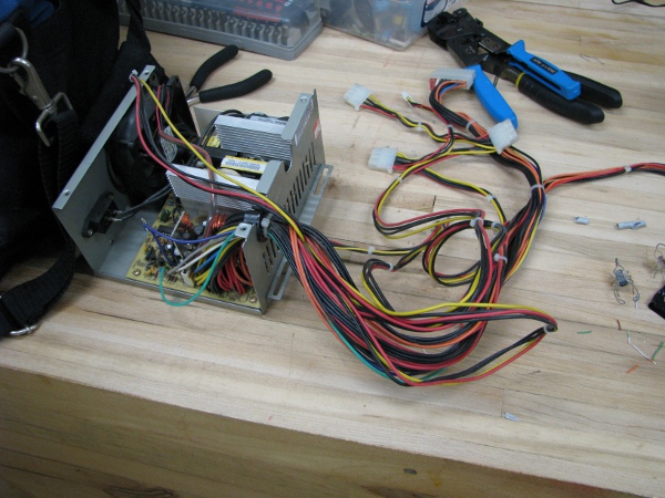
OK… Last thing we did was test our relay light and finally made sure the camera would run reliably on that 12 volt battery. I glued that photoresistor right to the front of our camera and that is dry now. We really need to test that. First I need some more wire. I really hate all the wire I am using. They are all very stiff. The problem is I don’t have any other wire, so I am stuck.. But I do have a lot of old power supplies from computers. Lets bust one of the broken ones open and steal some red and black wire.
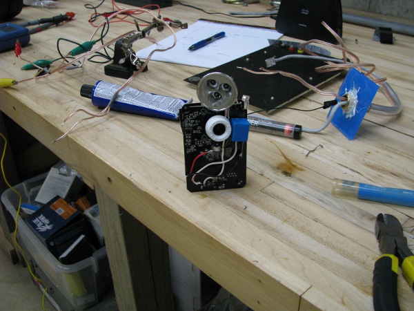
I solder everything up permanently. Connect the relay to the 12 volt power from our camera power supply, then I connect the light through the relay and pick 5 volts off the 5 volt power jack in the back. I position the light at the top the camera as it would appear in our water proof case. This is what it looks like.
I now have to attach our top with our cable assembly for power, transmission and network. I solder all the connections permanently.
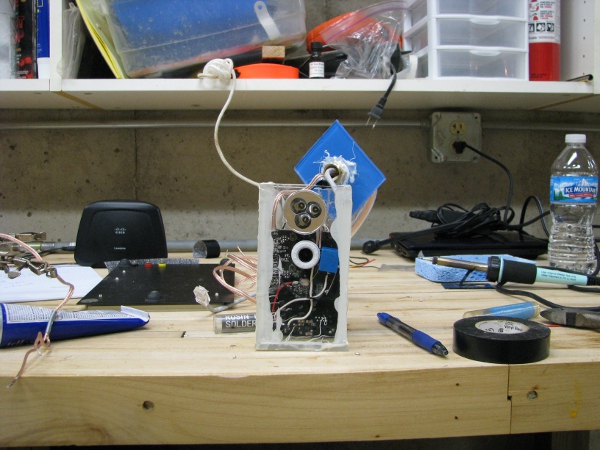
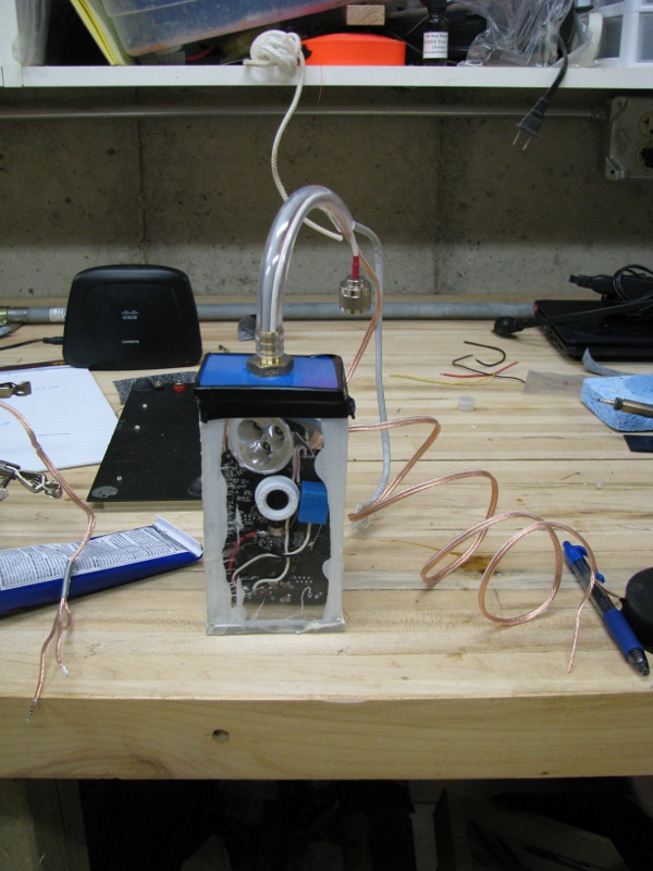
I slide it all into our case. It fits really nicely. A little snug, but that is good. I have trouble getting it in there because the wires are stiff and tend to spring back away from where I want them. Here is how it looks.
I can’t glue anything in place permanently now. I may have to take it all apart again as we have not tested our photoresistor that is glued face down on those LEDs in the front. As I tape the top on the light gets pushed off the plexiglass and now sits crooked. I make a mental note that I will have to spot glue that in place before putting the top on permanently. Here is the full camera without the antenna that we will be testing.
We are so close. At this point I really just expect everything to work. That photoresistor is right there up next to the LED, so we really should be good. I attach the camera to the power supply and watch it. Right away I see something that isn’t right…
The little LEDs are on, but our light is not on. Then something happens. I can’t take a picture of it, so I will have to explain it. The network activity LED (The red one that flashes, is tripping the relay. Every time that thing turns on and off the light blinks. It is blinking and blinking and I can hear the relay going off like a telegraph machine from the movies and with the light it is like a disco. It is kind of cool looking, but useless as we cant have it be that way.
I can see right away there are two things wrong. First I connected the light to the wrong leg of the relay. One of the legs is a closed switch when the relay is not active, the other is closed when the relay is active. I move that first and test. It is still almost the exact same behavior where the flickering LED is controlling the light instead of the steady LED right next to it.
I need to fix this. We are way too close. There has got to be a solution. In my mind I am thinking it may be a long time before we get this back into the case as this just doesn’t seem right at all. I may have to go back to transistors.
I don’t know if you have every had this feeling, I have it all of the time. When I run into problems, almost no matter how complicated, I always have this feeling like the solution is right their for me to know and I just have to find it from somewhere in my brain, it is like the solution is right there and I can get it. I have to think about this. The solution should be simple. I know we need more current and I want to pick that extra current up by the light. I remember our batteries weren’t very good at the beginning of this project and grab a voltmeter to measure the voltage from our 12 volt battery. Nope… 12.7 volts. That is not the problem.
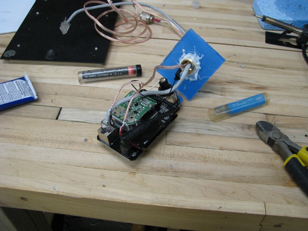
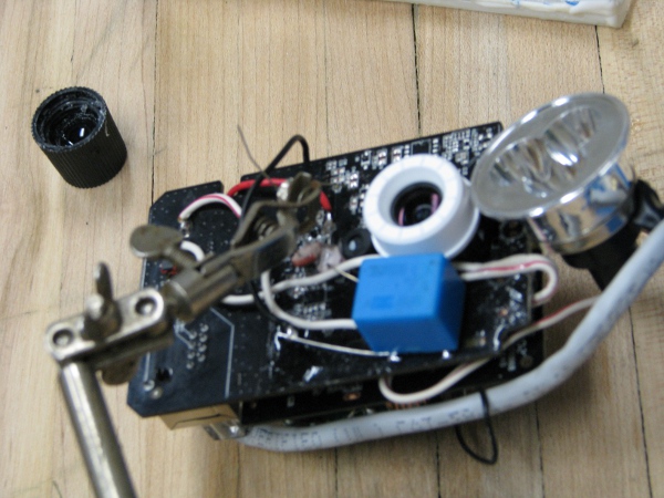
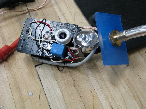
I can see a little blue light coming from through the glue so I decide to put another photoresistor and glue it face down right on the blue that I see coming through the bottom of that one photoresistor that is already glued down. I temporarily wrap the ends around so it is in parallel to the original. As it detects a little light, it should just dump that little extra current to the relay to make it behave. It will be a little ugly, but our camera is already very ugly. Here is what it looks like as I glue it in place.
Here is a better shot of what it looks like from a different angle after it is dried.
I test it and it is still exactly the same. That didn’t help at all. I need to add more current. I think, “who says we have to use a photoresistor for getting that extra current?” I will just add a resistor right across. It may cost us a little more power even when we are not using the light, but it should be a small amount. The added bonus of this is I get to do math to get me close (I don’t know anything about those photoresistors as there was no documentation with them so it was just trial and error all the way).
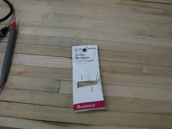
We took a lot of measurements with our ampmeter to understand how much power was required for different parts of this circuit. If I recall correctly we wanted to get 250 ohms from 5 volts to drive that relay shut. We are now using 12 volts, so that would bring us around 580 ohms or so to make it turn on the light. I just take a simple guess that if I put a 1000 ohm resistor in there, it just may do the trick. It may just tune the circuit to the output brightness of the blue power LED on the face of the camera. I look around through our resistors and really am in no mood to mess with the color coding because we already covered it and I am bored with it. Then I see this.
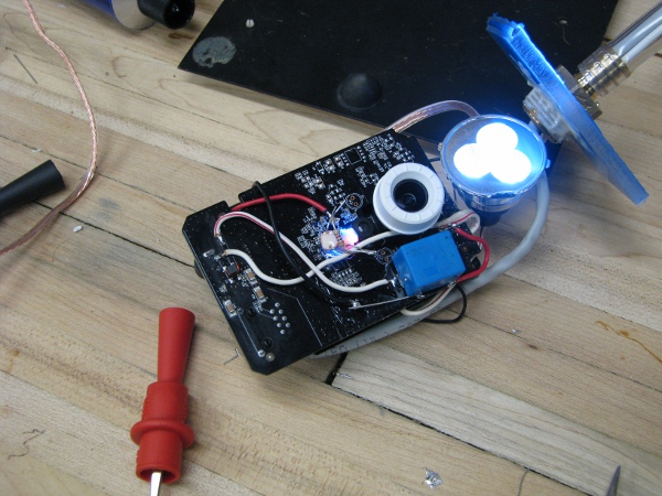
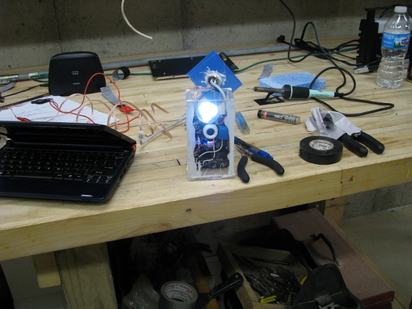
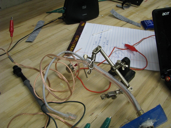
There were two left in that package, I used the other one for our circuit. I test it and now the light stops oscillating and just stays on, even when the little activity light is flashing. This looks really good. Here is a picture of what those three components look like all soldered together in series and glued to the face of the camera (I tell ya this camera won’t be winning any beauty contests, I think I will call it “frankencam” instead of “pondcam”). Notice the light is on and stays on.
If you look closely, we have two photoresistors and a 1K resister right between them. Now I have to test this to see if it all works correctly. I need to turn that light off with the software of the camera.
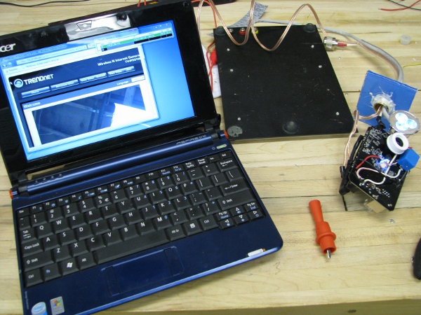
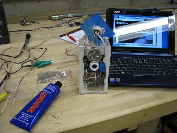
I grab the netbook and connect it up to the camera. Yes… It still works.
Note: When I first booted the camera up I could see it on the network and login to it but it didn’t show me an interface view that you have seen many screen shots of so far. I was so scared I accidentally shorted something out. I didn’t take a picture of it because I thought it was all over for the camera. Fortunately I noticed that as we were moving it in and out of that case, the two boards that comprise the camera were getting separated (they are connected together by nicely placed board connections that hold them together). I pushed them back together and it worked (I was totally relieved).
You can see from the above picture three important things: 1) The camera is working and correctly showing what it is pointing at; my workshop ceiling on the computer. 2) The camera light is on. 3) The little LEDs are on too. Now all we have to do is turn them off in the software and see if that drops the current to our relay and turns off the light.
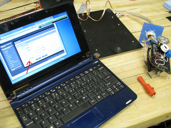
This is a picture of me turning off the LED in the software (The picture is really crappy and you can hardly see it so I put an arrow in there).
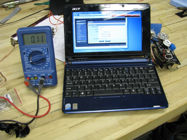
So… I turned off the light with the software (notice the light is, in fact, OFF!). I am so excited, we are ready to put this thing together again. One more test though, I want to see how much power that light/relay assembly costs us from the 12 volt battery. I connect my ampmeter with the light off.
110 milliamps???!?!?! Is that all. I am feeling so good about this thing right now. How about when the light is on?
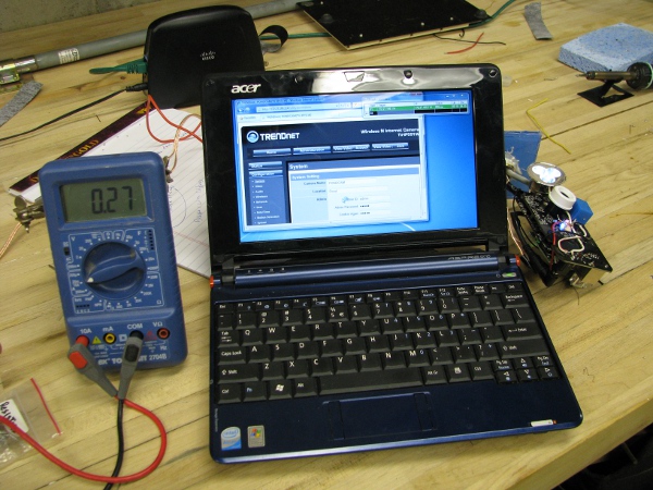
Gadzooks! 270 milliamps. Wow! That probably wasn’t the best way to turn on that light. Just to have that on more than doubles our camera power consumption. I don’t care though. I just have to remember to turn the light off when I am done looking at it. I wouldn’t want to leave that on all of the time anyway.
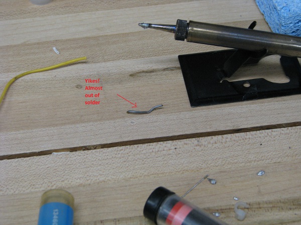
I think we are ready to put this all back together and the time for soldering/math and other complicated things that are hard to follow are OVER (At least I hope they are). One thing for sure is this. I am almost out of solder.
Let’s get this sucker back into the case.
Oh… That is nice. I want to permanently position that light so it doesn’t move though. I put three little dabs of Goop on the top and two sides of the face of the light, then hold it where I want it by using one of our empty solder containers to push the thing into the plexiglass. Here is a picture.
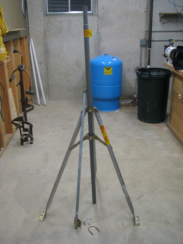
OK… That has to dry so I can’t do squat with it. I have to think of something to do to move this project toward its intended result. I have been asking myself a question for a while. And it is this. How am I going to keep this camera under water? If I stick this in water and it is water tight like I want it, it is gonna float! I thought about weights on the bottom of the camera, but scraped that idea before I got even close to attaching one. Let’s bring our antenna mount in from outside.
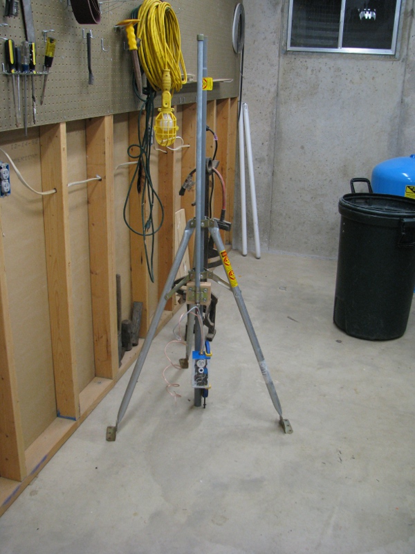
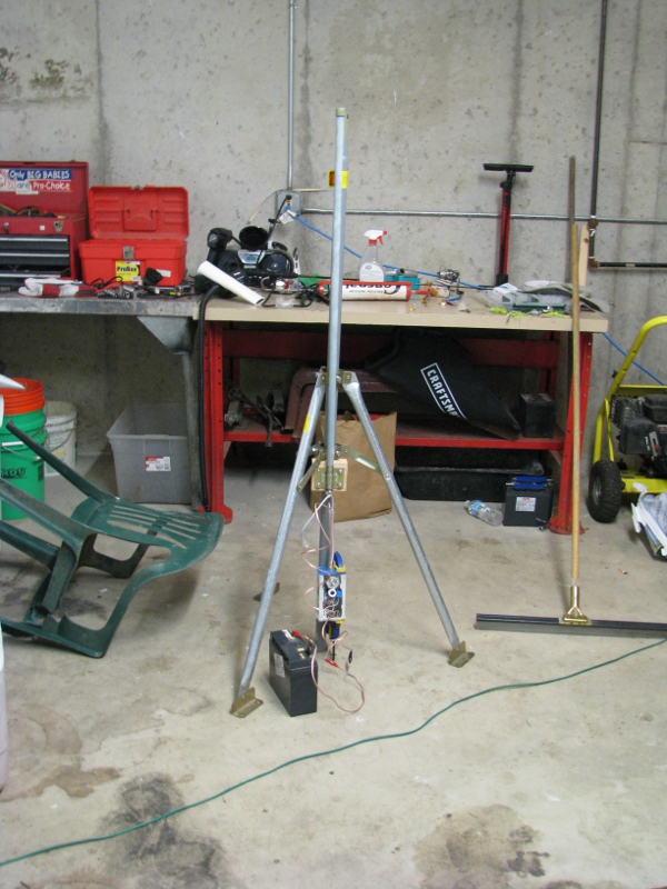
I like this thing. It used to be on my old house. I got that 10db antenna because I was planning on seeing how far I could get wireless to go across town from my old house (I used to do some work for a wireless Internet provider, I got an antenna like this to go for over a mile). My plan is to use these brackets to mount the antenna to the center pole and have our camera fastened to the bottom. Totally easy solution.
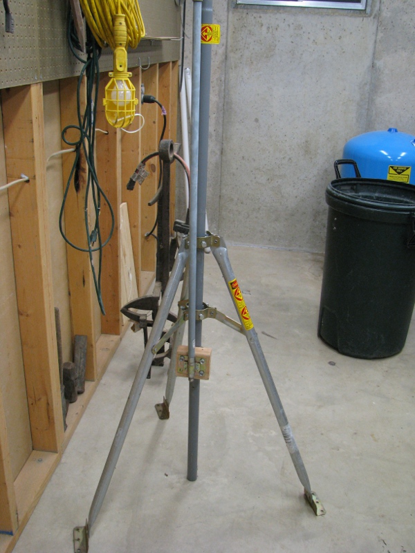
I cut a chunk of wood from a 2×4 and drill some holes in it to offset the antenna so it will clear those bolts that are used to secure the center pole. This is not what this mounting system is designed to do at all, but I can see right away it will work just fine. Here is where we are after I drill a few holes and put it together.
This is perfect, when we are ready, I will attach our antenna to the camera and then run our 12 volt power cables to our solar panel / battery power source. The plan is for the pondcam to be at the bottom, securely fastened to that pole under the antenna somewhere.
OK.. What now? I am waiting for glue to dry so I have to think of something to do. Oh… I know… Since everything is coming together so nicely, I have to worry more about our water proofing. The top of our cabling harness needs some glue, let’s squish as much glue as possible into the top of the harness (Remember the harness is going to be facing up. Rain will hit the antenna flow down right across that thing. If we don’t totally waterproof that, it will leak right into our camera from the cable assembly. That would be BAD NEWS! as it will flow right down right on top of our camera). Here is a picture of where I leave it overnight. If you need an idea of where to focus, there is a total mess of glue on the top of that tube that holds all of those wires.
It is the next day and all of that glue should be dry. I am thinking we really need to get this in the case. It is for several reasons:
1) It moves us closer to our goal of getting it into the water.
2) That camera is more fragile than just the boards and the camera that it mounted on them. They are plugged together and they easily come apart when I move it around which causes problems. And all of the wires, relay and light that are soldered to it; it is just one wrong move with having some wire touch the wrong thing and then bloop! dead camera.
3) Glue takes a long time to dry. I need to use glue to make it water proof. So I better get to gluing because this has got to get in the water ASAP.
We need to test our camera again, but in the case without gluing it. Why? I need to know if that antenna still works. I have pulled that little plug and messed with wires and moved it around. I need to make sure the connection to our huge antenna is working before putting that top on. Remember the connection to the antenna? I made that a couple of weeks ago during post 1. With all of the stuff we have done we could have totally compromised that connection for the antenna.
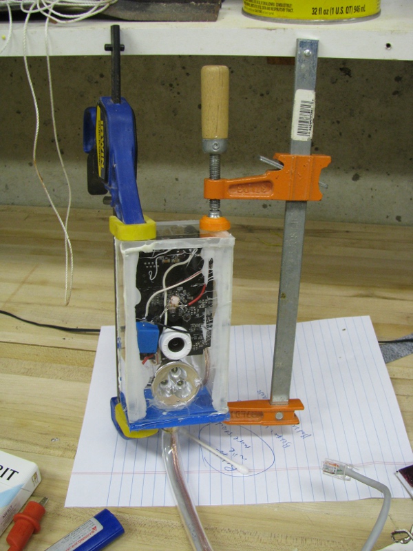
So I place the top on and clamp it down with a C clamp (There is a more modern word for this type of clamp I am sure, but I will call it a C clamp for now). And then I connect it to our antenna under the roof mount. Here is what it looks like.
It fits really nicely. Imagine that thing just plopped into water. The camera itself will be about a foot down. Out of the top will be our 12volt power wire. I am hoping putting this thing in the water is just really easy with this. I imagine just walking out to the pond, finding a decent home for it. Then plopping it into the water and attaching the solar panel / batter power assembly. I really hope it is that easy. I will be very disappointed if it doesn’t work out that way.
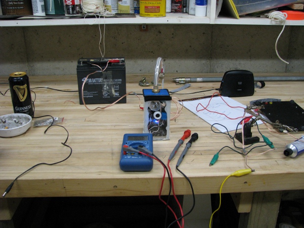
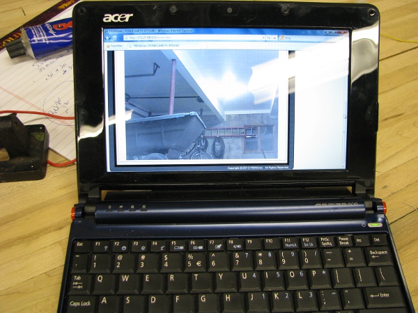
Next I grab the battery and some jumpers and bring it out the garage. Remember to test if that antenna is working I have to bring it as far away from it as makes sense (The garage is about 40 feet away and I am sure to close the door to the garage before testing). Here is what it looks like in the garage.
I look at that picture and I imagine it 1ft under water. Just looking for fish. I hurry up and power up the netbook to check it.
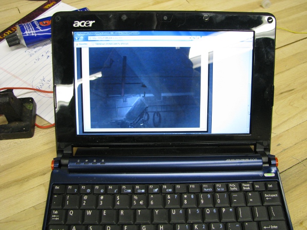
Yep… That is what I was expecting. I know what you are thinking, “Does the ‘Tim Light’ still work”? Let’s see. I go and turn off the garage lights. Then turn on the camera light in the software.
It was pitch black in that garage when I turned off the lights. I did check it with the camera to see if it could see anything. That little light is very bright. I can totally make out the back of the wagon and even the water hoses on the back wall. This should be able to see fish a few feet away from the face of the camera, even at night.
I am totally satisfied with all of these tests. Let’s seal up the camera and let it dry overnight. I add as much Goop as I can to the sides of the top of the camera. Remember how that water leaked after I epoxied the case together? I have to make sure this is really water proof. As I am writing this I almost want to put a water sensor at the bottom of this box to warn me, but that would add another two posts and I really need to finish this (Oh.. Just off the top of my head I can think of ways to have this project take an entire year). When I am done, I clamp it down with some C clamps and flip it upside-down so any extra glue would crawl across the camera overnight and instead will just land on the paper underneath.
An hour later I go back to check on how it is drying. I am in a totally hurry and want to put this in the pond tomorrow. It looks dry enough for me to I start smearing Goop along all of the edges where glue/epoxy is to make sure it is sealed really well. While I was doing this, the top slid right off the camera and glue started to get in places where I didn’t want them. I quickly put the clamps back on and continued sealing the edges. When this happened the light popped off of its spot glue and is now a little bit crooked. This sucks, but I really want to leave it this way so I can sink it tomorrow. The light was pretty bright, it may be OK.
One last thing. I really don’t like the way that Ethernet cable end looks in this picture. If that gets into the water while the camera is on I am not sure what will happen. I have been thinking a lot about how to protect that from water today because this camera will be sunk tomorrow. I decide to clip the plug and spread some Goop all over the exposed wire. I can put a new end on in a few minutes so it isn’t a big deal. I would take a picture of this, but it is too hard. I am really tired and need to get some sleep.
To continue reading see post 8.


Wow, Joe, just be patient so that a last minute hurry won’t lead to any problems!
If you can drill a hole in tempered glass for your wires you should try the glass storage containers that Paul recommended. I gave you a set for Christmas just like Paul’s.
The weird thing is that the waterproofing seems to be the only thing I did right (See the next post -8). I thought the rest was going to be easy and for some stupid reason the easy parts have been really hard and what I thought was going to be the one hard part (waterproofing) seems to be really easy. It is like my technical world is all upside-down. If the camera sprang a leak and broke at this point I would totally understand. Not being able to take my camera/battery/solar assembly more more than a few feet away from my house is what I don’t understand (actually what I didn’t understand… Again see the next post of more info).
Pingback: My Silly Pondcam – Part 6 – Light? | Joe's Lab