Monthly Archives: December 2015

You are browsing the site archives by month.

TOP SECRET PROJECT: CORHAKADA – POST 3

2015-12-10

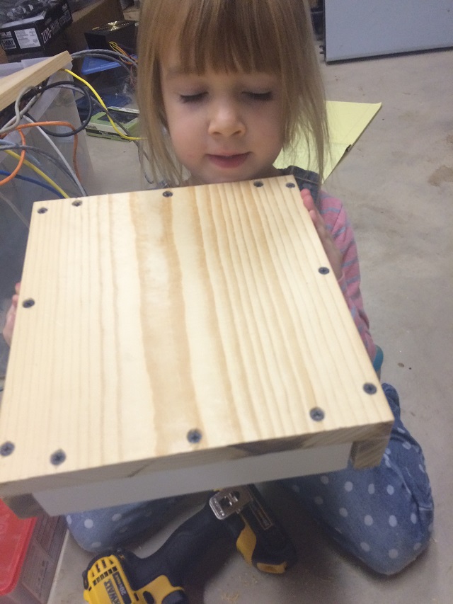
So I worked from home today and had a ton of stuff to do, but was really quick on finishing everything; paying bills, calling customers, assisting in the technical miscellany that comes up in my normal job every day. As soon as I was finished I called the girls down to open everything up and at connect things so I can do the final test.

IMG_2203

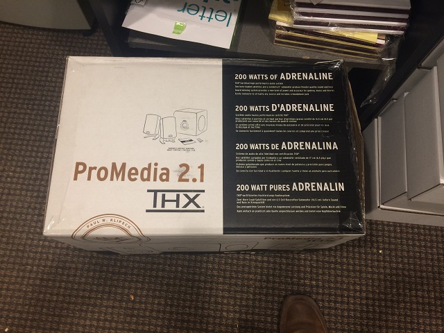
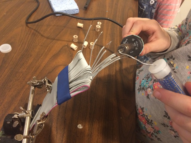
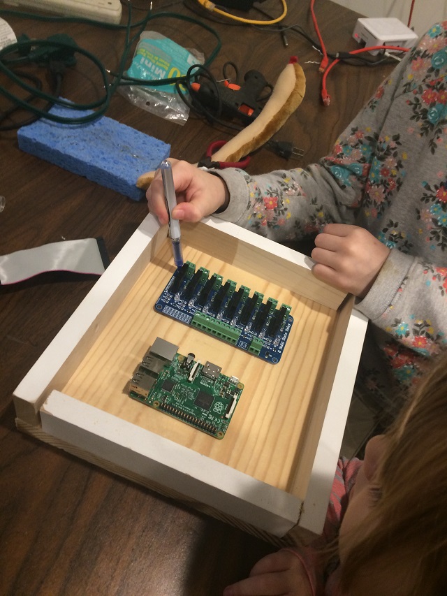
They pulled out the speakers and here is a quick video of us doing our sound test.

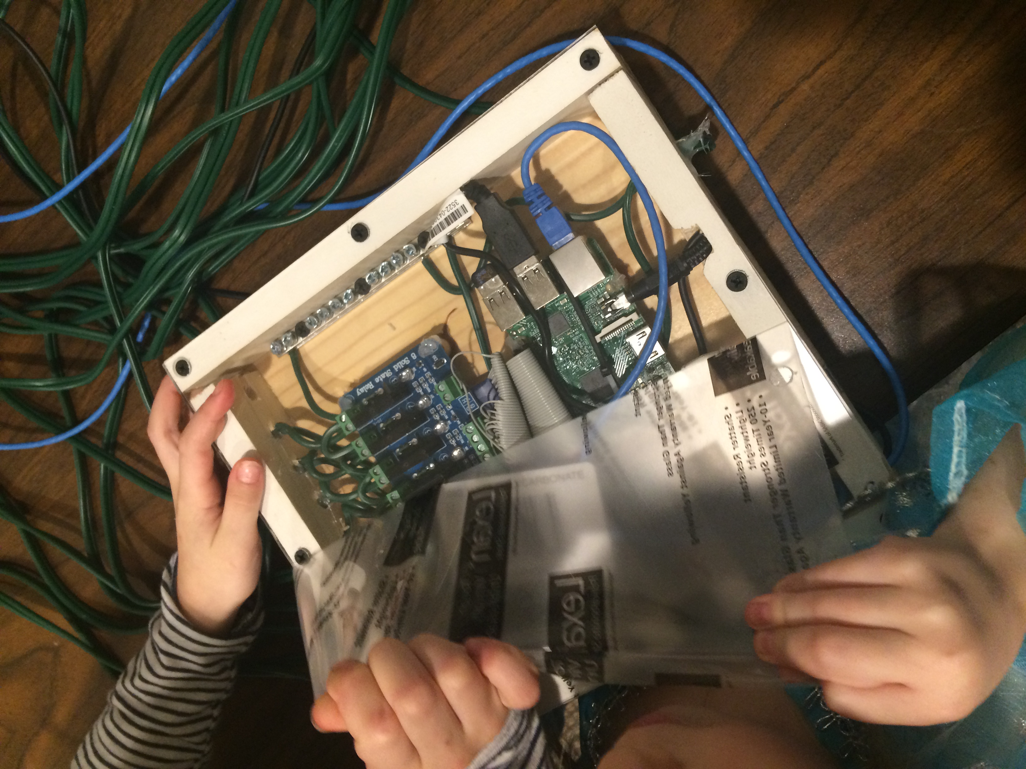
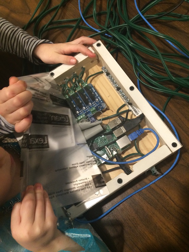
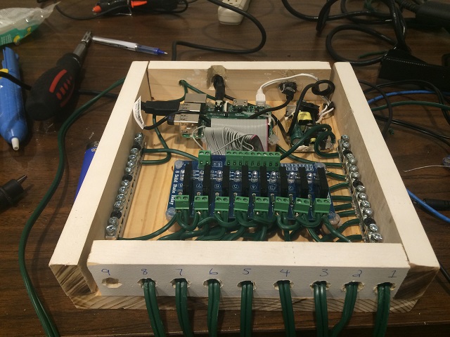
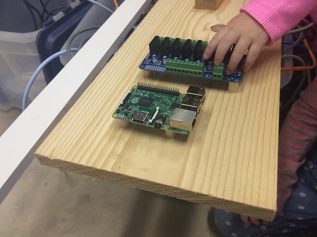
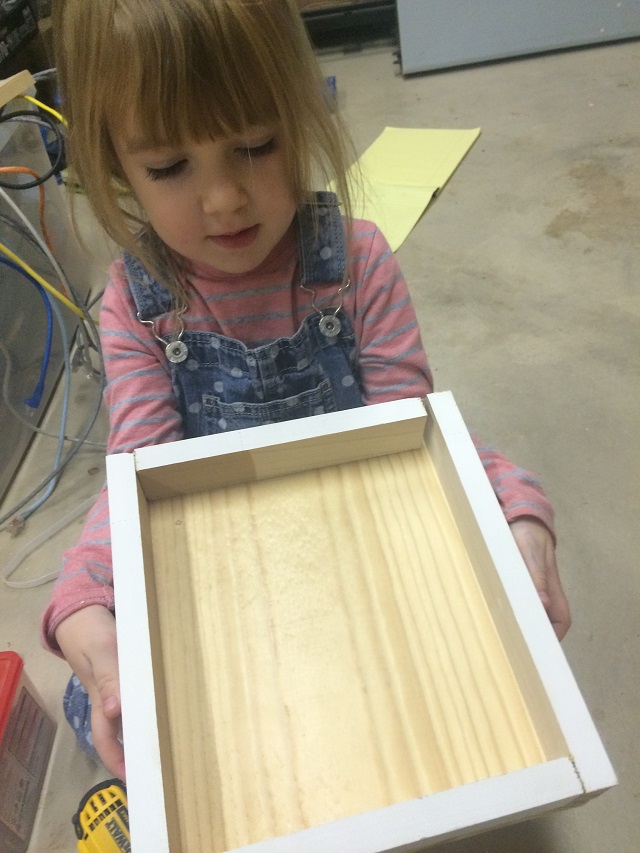
Now I never tested the actual daughter board. I have no idea if those outlets will work. So I start the program and test. This looks pretty good.

Well… I am very happy… Everything tested out OK and works the way I would expect.

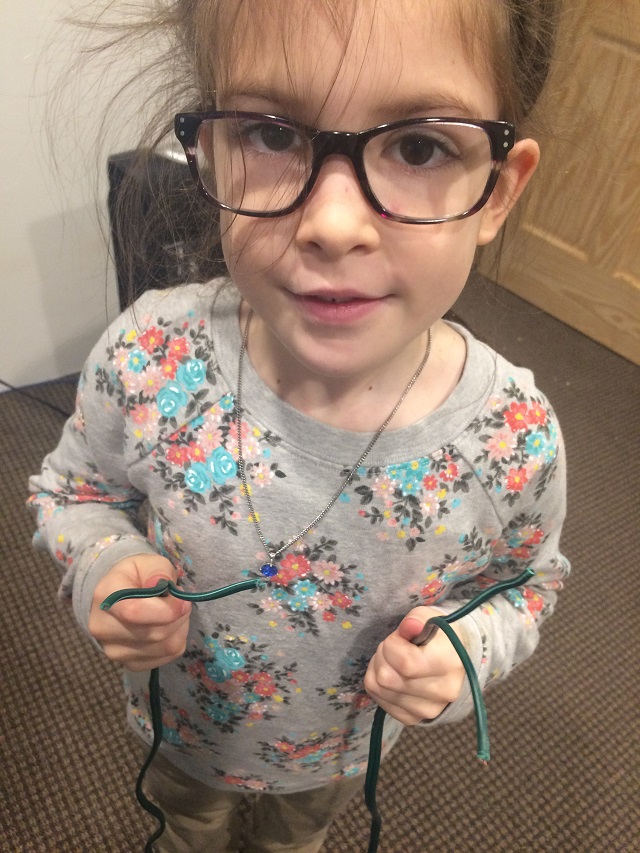
I told the girls that we needed a “break from this project” as it was getting boring and we should go hang Christmas lights in our sun room. They were all excited and started plugging them into the outlets to turn them on. I told them I wanted to be the one to plug them in because it was too dangerous for them to plug them into the wall. That didn’t deter them at all and they started plugging them in and it was a whole thing.

2015-12-11 – 10:29PM

Well… Today the boot drive on my home computer went bad and at a very bad time. I was on site at a customer site and couldn’t connect to it to get to some important notes for a project, but even after my wife rebooted it she said it was giving an error… Something like, “Insert boot disk blah  blah blah”. After dinner at my parents house I checked it and sure enough… ”

IMG_2207

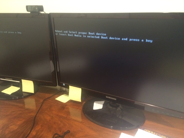
Oh… Yeah… No. No. No. that wont work… that wont work at all. I checked it… The boot drive is dead. The problem is all my latest notes on on that system, not on the boot drive, but on another set of disks that are attached to it… Oh well… When life gives you lemons…

There are a few things that are good about that. I will list them in order of importance for this project:

  1. I can’t work on my PC. That means I have to finish hanging Christmas lights tonight (I don’t like hanging Christmas lights).
  2. I wanted to get a cheaper PC to use for my desktop anyway. I am not a gamer or power user, I just need it to configure stuff for customers and document. I built that PC for a lab system originally with lots and lots of power to get things built out and tested for customers quickly… The only reason I use it for a workstation was when I was doing video editing for a web commercial. That has been done this past April… It is overkill for me now.
  3. I want to use parts from that computer, specifically the camera you see on the top. I want to make a video of Project CORHAKADA and put it on youtube. The iPhone 5 camera on my phone wont be as nice as that.

With all that being said… I am off to plug in Christmas lights. I don’t know why I have such an aversion to hanging Christmas lights. I like looking at them. I love Christmas. My shrink thinks I don’t like it because when I was a little kid my father died on Christmas Eve climbing down our chimney and got stuck.. Oh… Wait  a minute that wasn’t my father… he is still alive. Oh yeah… That was from that silly girl from Gremlins… WORST CHRISTMAS STORY EVER! I am not sure what Chris Columbus the screen writer for this movie was thinking.


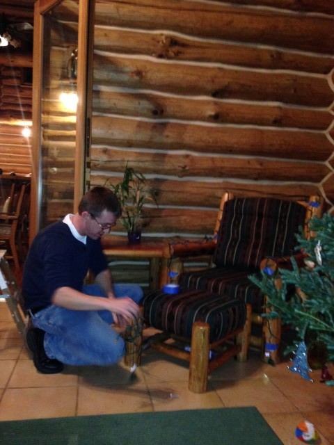
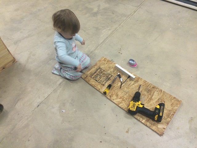
Anyway who cares if I don’t like hanging Christmas lights. It has to be done so I do it. Here is a picture of me hard at work.

IMG_6927

I know what you are thinking. You are thinking, “Joe has gone off the rails and now he is just showing us everything he has to do because he is bored and his wife is making him do things he doesn’t like”. To that I say, “PISH POSH!!!” There is a reason for this madness. And here it is:

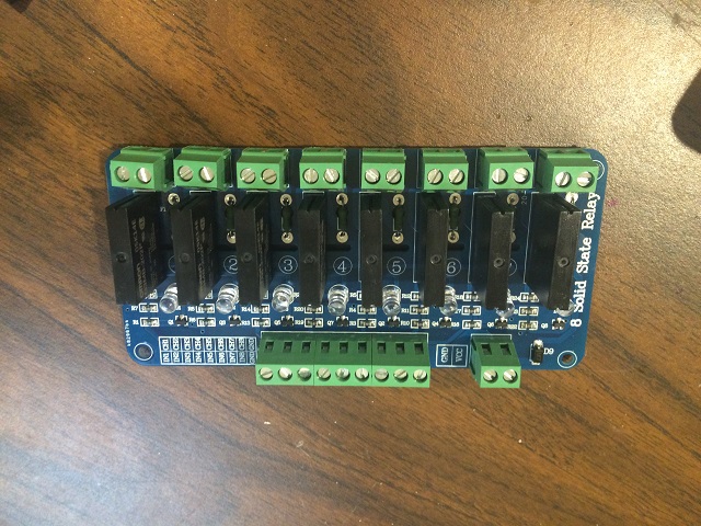
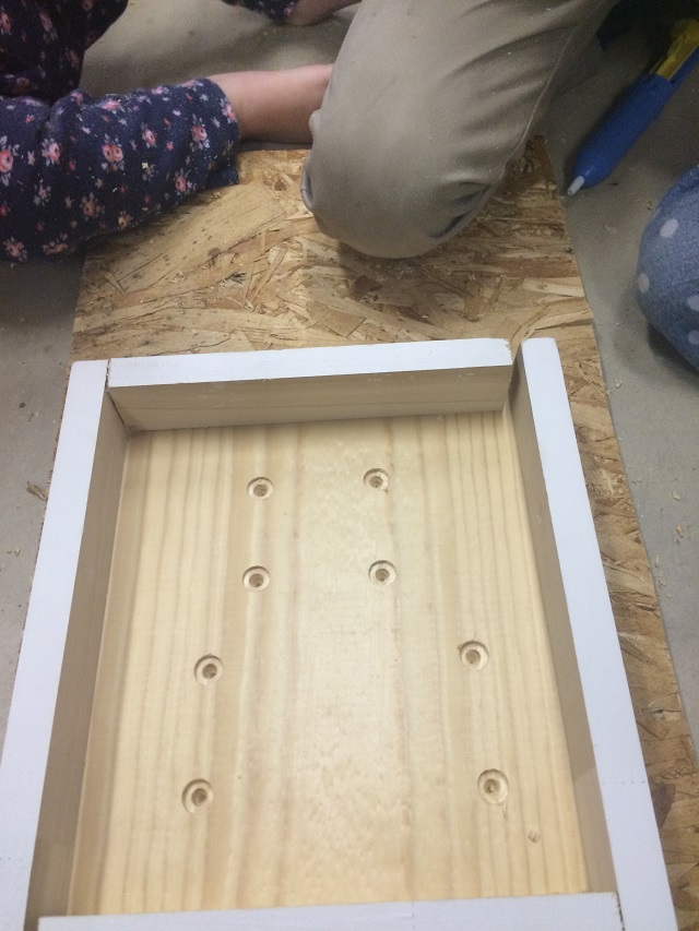
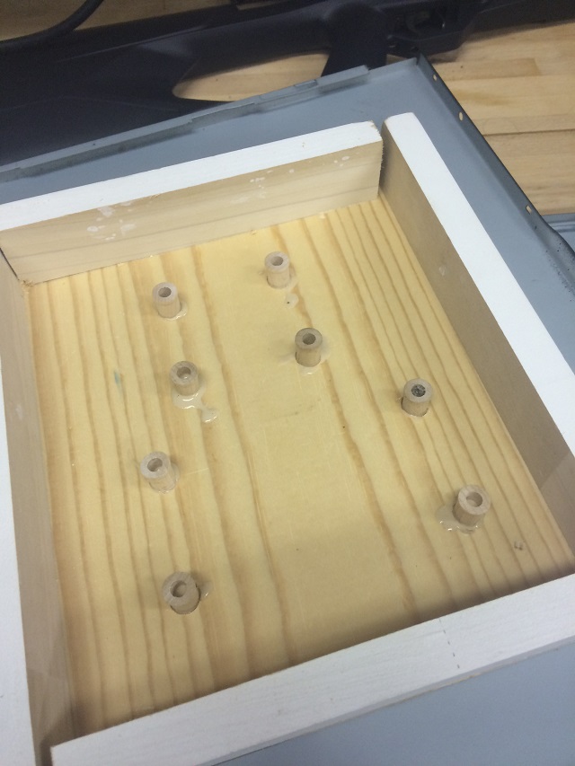
  1. I have 120VAC outlets on my project CORHAKADA.
  2. In my sun room I have 8 strands of Christmas lights placed strategically on the tree, around windows and even on the furniture.
  3. I am going to connect all of these together and attempt something that will make my kids very happy… And make myself laugh and laugh.

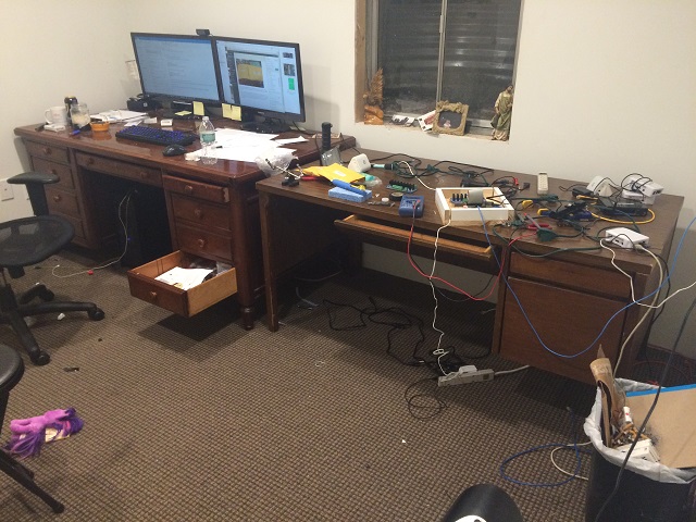
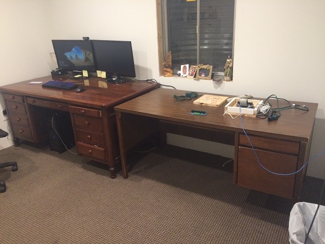
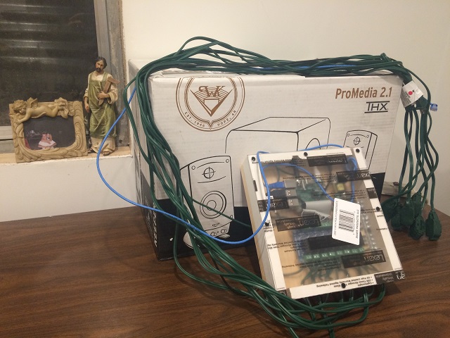
Let’s get going…. Her is a picture of the room with all of the lights in place. Only the Christmas tree is on because my wife did that part a couple of weeks ago. Nothing else is plugged in.

IMG_2211

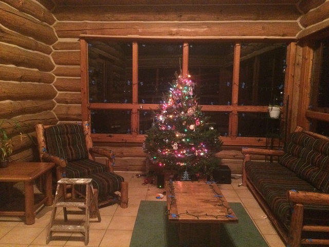
I taped lights to the windows, chair, couch, table, etc. I first tried electrical tape… It all fell off the next day. Then I used blue painters tape. That worked much better.

Here is what I am going to do:

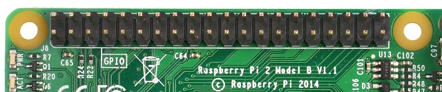
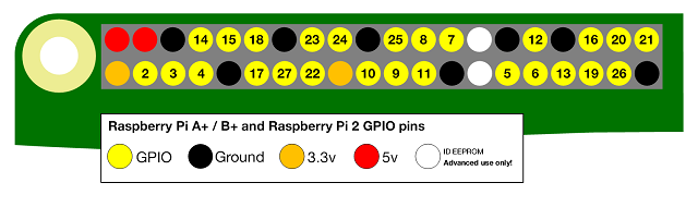
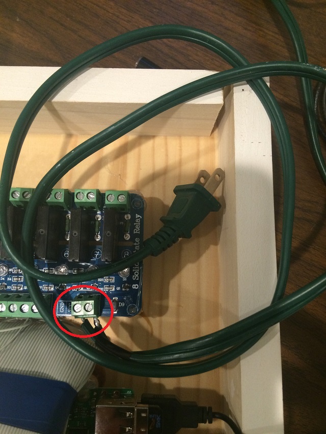
  1. I am going to take the power cord from our device and connect GPIO0 to the Christmas tree.
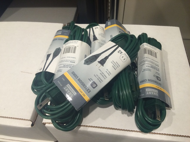
  2. I am going to use the spare extension cords we bought earlier and connect the rest of the lights in no particular order to the rest of the lights on the windows and furniture.
  3. I am going to connect our speaker system to the motherboard.
  4. Then I am going to experiment to see if I can get something going that my kids will think is just great.

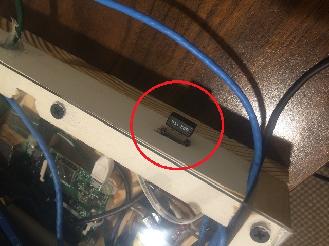
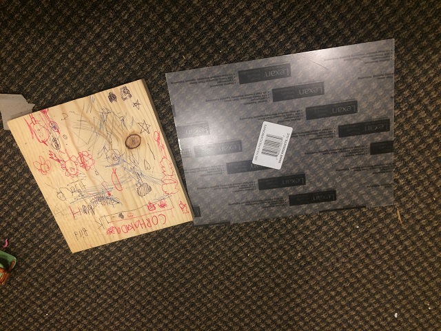
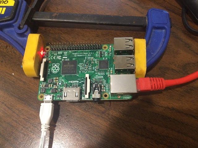
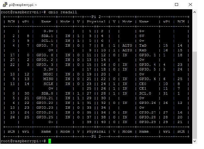
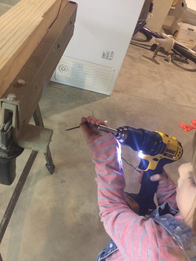
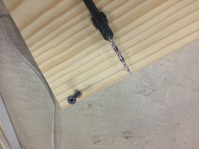
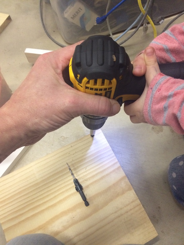
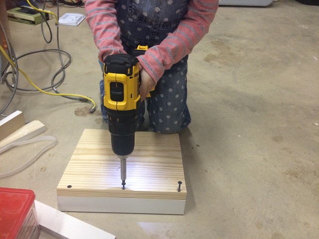
Oh… One more thing… Remember me and Kasia carving out the case to make that extension for a USB port? Yeah… Well I had to stick a wireless adapter in there so my project can communicate to a notebook in the back of the sun room where I am sitting now. I need to configure this first… It is going to be tricky because all of my notes on how to do that are on my computer that won’t boot. Grrr…

IMG_2208

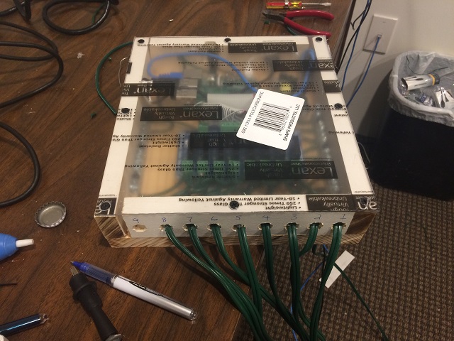
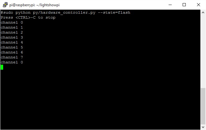
OK.. That is done… Let’s do a test.

OK… That worked all eight channels. The rest of the stuff is just boring tedious things. Testing sound, etc.

2015-12-12 – 11:15PM

Happy Birthday Mom if you are reading this.

I know… I know… It is super late for most people… 11:15PM what am I doing writing? Well… I already went to Mass earlier, the wife and kids are all asleep. I don’t do actual “work” on Sundays… So I can do what I always wanted with this project. I can stay up until I am literally too tired to work on it.

My hard drive on my computer died yesterday… I went to Fry’s with the kids today… They didn’t even notice I bought them their Christmas presents while we were there! Too fun.

IMG_2214

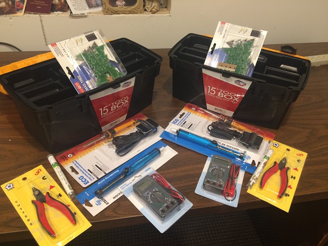
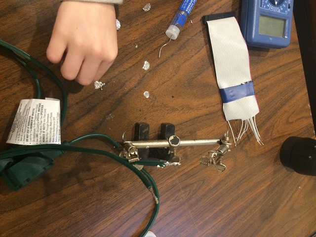
Soldering irons…Solder removers… Wire clippers…. Multimeters… Toolboxes… And most importantly… The Christmas morning project (if they want to put them together) little light up Christmas trees they have to solder together!!!….. Crap! I just realized I need to get a couple of 9 volt batteries to power those little Christmas trees up.

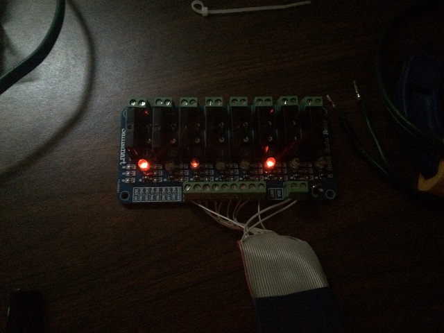
Anyway… I also bought a new hard drive at Fry’s and it took a while for me to get back on line. I know… Boring right? But… I did need that to get my computer back on line and continue project CORHAKADA. Here is where we are with that project. I figured out how to make one of those channels light up when the motherboard “talks”.

2015-12-13 – 1:13AM


That was pretty good. I don’t know why it sounded like someone was taking a bite out of an apple after, but it was OK by my standards.

Now there is probably a way better way to do this, but I am just going with what I know. I have a script that allows me to make any channel on our daughter board talk. My setup works like this:

  1. I have a text to speech synthesis program that will upload any text I type to a Microsoft cloud server. That server will spit back out a MP3 file that I can play and push through the program.
  2. I control which channel they go out to by a config file that says basically “Only use channel 0 or channel 1 or any channel I choose for the lights”.
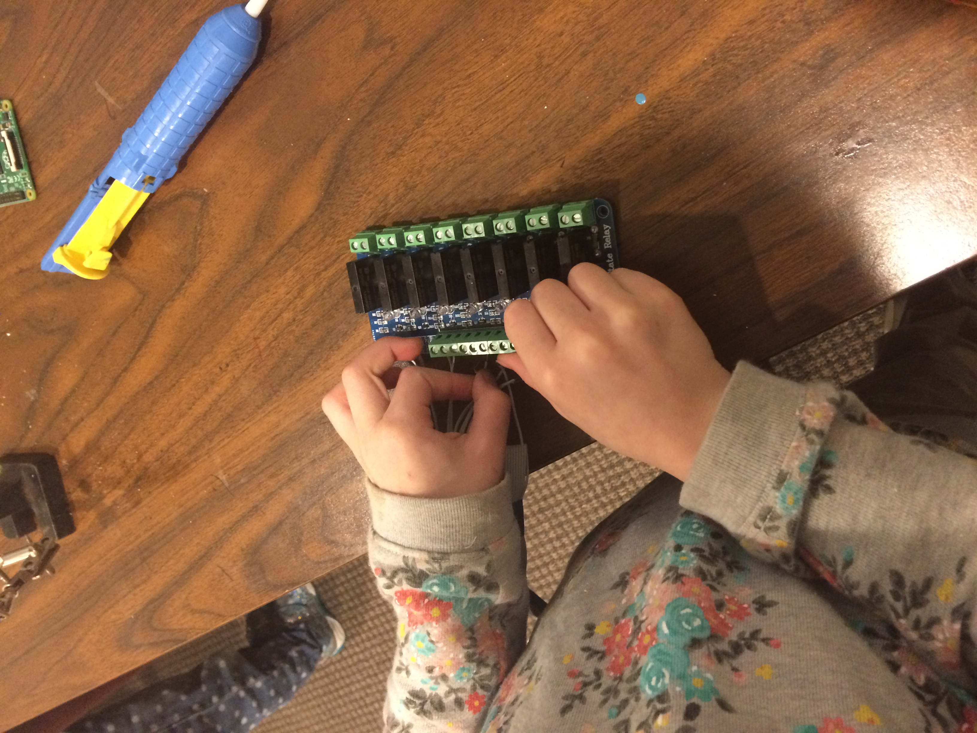
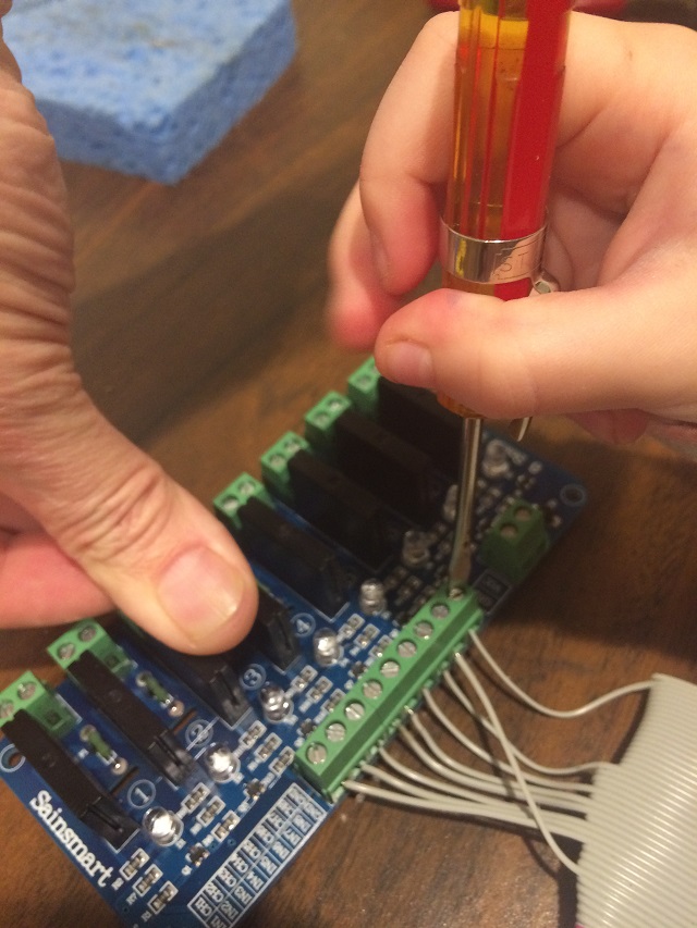
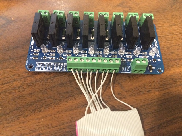
  3. The outputs of our “daughter board are connected to lights that cover different areas of my sun room.

With all of that put together I can run a script that looks like this:

./tree.sh “I am a Christmas tree.”
./big-window.sh “I am a big window.”
./couch.sh “I am a couch.”
./table.sh “I am a table.”
./chair.sh “I am a chair.”
./lower-window.sh “I am a lower window.”
./extra.sh “I am just some extra lights daddy had lying around.”

That is pretty simple stuff… Here is what you get.

2015-12-13 – 2:33AM

Well… I got my wish… I am literally too exhausted to do anything more. Good night.

2015-12-13 – 9:22PM

It was another long day. I had to finish fixing my computer so I could do real work tomorrow. But once that was done it was right back on to project CORHAKADA.

I didn’t like that each window or piece of furniture sounded just like the Christmas tree, so I used that program called “espeak” to generate those. The Christmas tree sounds more “human” the rest of the furniture and windows are robotic, but with different voices (different pitch, frequency, etc.) it was a tiny bit of work to get that right.

I wrote out a script for the Christmas tree to talk to my kids. I was able to test it a couple of times before we left for Grandma’s birthday party. When we got back… I just decided. Time to finish this project. No explanation necessary. Here is what the project was all about.


OK… Let’s call this project done. I am looking forward to the next project that I come across to teach my girls. Can’t wait for them to open their Christmas presents. Go STEM!

TOP SECRET PROJECT: CORHAKADA – POST 2

2015/12/06-9:13PM:

OK… This morning before leaving to Mass I couldn’t believe it. Delivered at my door were these:

IMG_2171

Those are my new daughterboards. I am very surprised. Mike ordered them at 3:44PM on Saturday… I got them delivered at my door at 10:00AM Sunday… I wasn’t expecting that. It put me in a really good mood all day.

I have been trying to teach my daughters that with any good project the most important part is “clean up”. Without cleanup you can’t start any new projects because everything is such a disaster. And with this particular project we will be working with some high voltage (not that high… but enough to really hurt someone) so making things clean and tidy is imporant. Here is the mess we have left after yesterdays fiasco.

IMG_2172

It is a disaster… I have to work tomorrow and have a lot of work to do for customers before I can start back on the project. This entire mess has to be cleaned and organized.

Oh.. By the way… The first daughterboard is dead. I asked Hannah if we should throw it away or save it for spare parts. She said, “Save it for spare parts”. Smart kid. If we blow out one of those driver transistors for some reason, I think all 8 of those are still good on the broken daughterboard. I wouldn’t trust anything else on that board except maybe the connectors. I just have to remember to mark that sucker as “BAD” with permanent marker as visually we can’t tell the diference between a good board and a bad one and now that we have three of them floating around the office it could be a problem especially with a bunch of kids milling around through the whole thing.

Crap… I have to clean this up all by myself because the kids are in bed. Uuugh!!! Oh… and we used a hot glue gun to place the old broken daughter board in our case. I have to figure out how to remove that.

2015-12-06-10:30PM

Now that is more like it… Ready for work tomorrow and now I know what to have the girls do next. Swap out the fried daughterboard for the new one.

IMG_2173

2015-12-06-11:27PM:

I am thinking about what I can have the girls do tomorrow. I did notice that when working with the “hot glue gun” it isn’t really hot. I need them to remove the broken daughter board from the system. I thought about this a lot tonight and I do have one of these.

IMG_2174

Now I don’t use that heat gun a lot, but I do remember that it can get so hot that the tip actually turns red. It seems dangerous. But we are talking about teaching my girls STEM! They may get a little burned but it is worth the risk. I am going to have them melt that “warm glue” gun glue right off that daughterboard and they are going to install a new one. Wired correctly (no high voltage though… I will do that part) so we can see those pretty red LEDs light up when we run the program from the motherboard.

SPECIAL NOTE ON HOW DANGEROUS THIS IS:

I wanted to break from my normal writing to actually mention to anyone who doesn’t know that this project is actually dangerous for children. My kids are using power tools, soldering irons, and eventually this device will be able to output voltage that would shock and possibly kill any one of us in the wrong situation. With that said… Go ahead and definitely try this at home, but make sure you understand what you are doing and watch your kids when they are around the device and tools, especially when you put VAC120 into it. GO STEM!!!

2015-12-07 – 9:24pM

So I had to work all day and didn’t get back until late. I had the girls use the heat gun and swap out the broken daughter board. They rewired it and now we have this.


Based by what I saw on with the multimeter testing this is what I was expecting. Two flashes for each light sequentially. Basic stuff. Pretty boring, huh?

Well what if we spice things up??? Let’s make this sucker talk.

Now I know what you are thinking… You are thinking, “Oh by all means make it talk, but don’t make me read through a ton of troubleshooting you have to do to get that working!”. To that I say… Request granted. The girls won’t be needed for this part as it is too complicated and guess what else? I already have all the code necessary from another project I worked on this summer. As a matter of fact I have a system image for a talking network monitor I built this summer that I will just download into the flash card on the unit and we will run with it.

2015-12-07 – 11:45PM

OK… Going with the system image of my talking network monitor didn’t work. Apparently my temperature sensor, which we don’t need for this project, was on GPIO7 which made that last light not light up and was sending me emails with the subject line “** PROBLEM Service Alert: Computer Room/temperature-sensor-monitor is CRITICAL **”

It is a whole thing. Instead I have to integrate the text to speech system into the original system image we already saw work. I will mess with that now.

SPECIAL NOTE: I have been an IT guy for over 25 years and it appears to me if anything needs sound I will have a problem with it. I think nice sound is my curse as it always gives me the most trouble. I know audiophiles and they have no problem with sound. I would like to be an audiophile too, but when it comes to making something “sound right” I just haven’t had good luck with it.  As a secondary goal of this project I will be pushing the envelope on making this silly little beast sound good.

Now I boot back up with he image we were working with earlier and install a text to speech program called “espeak”.

Here is an example of very basic text to speech.

There are quite a few problems with that, the first thing I need to iron out is I want those lights to flash like the box is actually talking to me. Let’s figure that out first. I want at least a couple of those lights to blink when the device talks.

OK… Here is what you are seeing…

The lights here responding to the voice but there are several problems:

  1. I don’t want the voice to go through the 8 channels. The software I use to drive those has this HUGE delay.
  2. Also if you notice all 8 of those LEDs are lighting up depending on what is said. I don’t like that either. I want a dedicated channel for voice. Those 8 are going to be used for something else.
  3. I hate the voice. I don’t want a robot. I want it to sound more human.
  4. Oh… And it isn’t loud enough. I want the voice to be loud.

2015-12-08 – 9:00PM

That is quite a list. Lets attack the volume first because it is easiest. I want to make sure I have a lot of control over the range of volume this produces. I also don’t mind it being obnoxious, so after mass tonight (Holy Day today… Feast of the Immaculate Conception. Yay!”) I went to the store and picked out the loudest most heavy sounding speaker system for a computer they had.

IMG_2188


Next I am going to attack the voice quality because I have done that before. It will take me a while and I won’t bore you with the details, but it has to do with uploading the text to a specialized translation site from Microsoft. It is a very crazy thing where I can actually have the text translated into a few different languages before being output. For now I will just use English.

For this I didn’t attach the new speaker system to it because it is so late and I want the bigger girls to help unbox and connect it and they are asleep. I had the computer say this because my 1 year old (Kasia) was demanding that she hang out with me. This ended up freaking her out and she was happy to go upstairs to mommy.

That is pretty good. Better than the robot voice for sure. I didn’t put it through the program to light those LEDs because I don’t want to have the text to speech work that way.


So here is what is left for me to figure out before I wrap this project up and play a video of the final project:

  1. I want a separate channel… Or better no “channel”, just an output just for when this system talks using the text to speech synthesis.
  2. I need to wire up the 8 channels so they can control 8 – 120 volt devices that I will be connecting to it.

2015-12-09 – 10:32PM

I am out of time and don’t have the luxury of giving too much detail (I know… I know… Everyone is sad because they love the play-by-play… Just kidding… I know no one is sad). I have two very important customer projects to work on and it is way more important for me to be obsessed over someone else’s project than my own because well… I can’t do any of my projects unless I have money… Motherboards, daugherboards and speaker systems don’t grown on trees. So let’s wrap this puppy up and call it done.

So I had to drop the 9th channel idea for the voice and handle that the way with all of the channels like we saw earlier. I will have to live with the delay (I tried to resurrect a component off of our fried daughterboard, but there is nothing on there that is good anymore… I planned to write about it too, but it is a no go so we will have to throw that in the garbage… no spare parts from it).

The other day I had to go to Menards and while I was there there were super cheap (like under 2 bucks) extension cords. I bought a bunch of them.

IMG_2197

That picture is deceiving… I bought way more than that, but you get the idea.

I drilled holes in the side of our case (9 of them because I was hoping to figure out that voice channel back then) and marked them for each  channel. I chopped the plugs that go into the wall off so I only have the outlets. I stripped, measured and tinned each end.

I grabbed a power supply for a Raspberry PI and busted it open and took out the power supply inside it. I used the hot glue gun to fasten it to the case.

I bought a couple of these so I could connect all of the 120VAC inside the case.

IMG_2186

I also grabbed an extension cable I had for audio to bring audio out of the box (I had to carve out the back of the case a bit so the plug would fit. I also chiseled out a place to use a USB extension to bring a USB output on the case itself. I don’t want to have to open it to connect anything and it will have a USB wireless adapter connected to it at some point (Maybe not today… but at some point). Here is a picture of Kasia helping me chisel stuff to make the box (that was poorly measured) have everything fit.

IMG_2193

The girls were totally much more interested in playing with the leftover boxes from the Christmas presents I bought for customers than anything having to do with top secret CORHAKADA They did this when I wasn’t looking. I am not sure what is going on there, but they seemed happy.

IMG_2192

Anyway… lots of drilling, a little carving, lots of soldering by me (I did a huge amount after the girls went to bed)… We have this.

IMG_2195

This is how it is connected: On the right are all of the neutral. On the left is the power that is fed to each of those eight channels. The idea is that as each GPIO is told to turn on… They will turn on.

Now there is HOT HOT HOT power going through this system when it is plugged in. I know it is a fire hazard because it is made of wood, but I don’t have time to mess with any of that. I just don’t want my kids to get shocked so I have to put a cover on it.

When I was at Menards I bought some plexiglass. I want to be able to see all of our hard work after this thing is done. I did keep the girls busy with decorating the top. Which would you choose for the top? Clear plexiglass or their decorated top?

IMG_2196


I chose clear plexiglass. I am sure the girls wont mind that I used that. I carefully cut the plexiglass and drilled holes in the top to fit on our case. The end result is this.

IMG_2198

Now I peeled off the back that is going towards the case and left the top to be peeled off for the girls tomorrow. I want them to be able to peel that back themselves (even the baby can help because it is safe) and see what we all did together. It will be HUGE!

I did a quick cleanup. VERY IMPORTANT if you try anything like this. Don’t leave cut power cords lying around the house. These go in the garbage in the garage, not the garbage can in the house (I just know the baby will figure out how to plug that into the wall and I just know she would stick the other end into her mouth… CLEANUP! most important part of a any project, but especially a project like this).


IMG_2199

So here is where we are… I was in a rush… After frying the first daughterboard I did my best to really figure out how to get everything connected. I didn’t test this… I just assumed I knew what I was doing. I didn’t even plug it in after putting all the wires in. Tomorrow I will have the girls unbox the speaker system, pull off the protective layer on the cover and plug it all in. The next post will be the final post (I hope) if I don’t run into any problem that is worth writing about.

IMG_2200

Finally… Did anyone figure out what this device does yet? I told my wife tonight and she was pleasantly surprised. That is a really good thing. She never is interested in any of my projects, but this one she likes. She doesn’t even read any of my blog posts. For example… I could say:

My wife is the neatest person I ever met and I am so happy I married her. I look forward to every day because she is so great. I brag about her all of the time with friends and family because she is so good at being a mom. I tell everyone that I “love being married” because I remember being single (I loved being single…. but being married is so much better). 

And she would never know.

To continue on to the next and final post on PROJECT CORHAKADA click here.


Top Secret Project: CORHAKADA

Wow… It has been over two years since I actually typed anything on my own blog. When I just logged into it, I forgot my password and was pretty amazed that is was actually still up.

OK… So let’s forget about my neglect for my lab site and get right to it.

About a year ago my wife said to me, “I am worried about our girls getting enough STEM education because I am just not good in that area.” For those of you that are not up on the term “STEM” it is an acronym for Science, Technology, Engineering and Math. When my wife said this to me I was totally perplexed. How could she think that the ball would be dropped when it comes to my FAVORITE stuff! Out of all education that is the only stuff I like. Literature… it is OK I guess, but I read Steinbeck and thought it lacking because… well… there were no gene edited dinosaurs, no robots, no laser weapons. Oh… And what crappy endings. Seriously? Literature? Who cares?

So… Back to my wife an kids… They need STEM. So… What better thing to do that a super secret project with a cool code name that has one of these!

IMG_2114

That is a “SainSmart 8-Channel 5V Solid State Relay Module Board for Arduino Uno Duemilanove MEGA2560 MEGA1280 ARM DSP PIC”.

I know what you are thinking, “What the heck is that and why would something that looks simpler than than the inside of my toaster be interesting to me?”.

Here is why… If you look at the picture, you will see the green bar in the middle / bottom of the board. Those are electrical connections. If I can figure out how to put a little bit of voltage in there (at my command of course) the little green connections on the top will output lots of power to do something interesting for the project. “Interesting” is not always POWER… but for super secret project “CORHAKADA” it is necessary to have POWER!

From now on, instead of calling this the “SainSmart 8-Channel… blah… blah… blah…” we will call it the “Daughterboard”.

Yeah… I know what you are thinking. We live in the age of “fundamental transformation” where sex doesn’t mean anything and certainly shouldn’t be applied to inanimate objects nor to human beings, but we call it a daughter board around here despite what the culture thinks… I have three daughters and they like Cabbage Patch Kids, stuffed animals, tea parties and all sorts of crap that I don’t care about. But they also like “Daughter Boards”. Enough said except, “Go STEM!”

Now I know everyone is curios and wants to know what the project really is. Well… Eventually if you keep reading you are going to figure it out. But my goal is to keep my children in the dark about it until it is as close to finished as possible.

OK… The next step is to show the Motherboard. For that we will be using a Raspberry Pi 2. This is a cheap little computer board (35.00). It really is an entire computer on one little board. It has a video out, networking, USB ports. It is really versatile.


IMG_2113

This is actually a broken Raspberry PI 2 that I have. The reason you see the c-clamp on it is that the clasp that holds the memory card in is broken. So that is one thing we need to figure out.

Another thing you will notice about it is this.


gpio-pins-pi2

That is a GPIO header. We are going to connect some of the pins on that guy to our daughter board. The problem at this moment is that neither the mother board or the daughter board came with any schematics so I have to look it all up on the Internet. In my initial searches I kept coming up with this…

gpio-numbers-pi2

…which isn’t much better, as I would expect to see something like a map that will tell me which of those pins are the actual GPIO pins and what number they are associated with so I can command the daughterboard with software on the motherboard. More on this later. The girls are ansy to get started.

Even thought I don’t know what pins will go to what, I need a way to connect them. I never did find any cables on line that would work easily, but I have a ton of electronics junk lying around so I am sure I can find something. That GPIO header looks a lot like an IDE interface to me, let’s see if I can find something that will work in one of my bins. Here is a picture of my hard drive connector bin.

IMG_2155

Yeah… I am pretty sure we can find something that will work in there. I rummage through it and after a few seconds I find an old hard drive cable. The problem with hard drive IDE connectors and this GPIO, although both 40 pins, IDE connectors are usually keyed. A lot of the time they have a filled in pin in the middle to keep people from putting them on the wrong way. Here is a picture of what an IDE interface looks like on a regular computer.

IDE

We wouldn’t want it to be keyed. We need all 40 pins. So I take a closer look at one of the connectors and it looks like we are good. All 40 are not blocked.

IDE-CONNECTOR

Next step I need to separate those individual wires on those ribbon cables. I know from experience you can’t just manually separate them because the wires will come right out of the insulation and it will be a disaster (I don’t remember why I know this, but clearly I have tried it before for some reason). So I need a razor blade. This will not be a job for a kid. So… I cut the ribbon cable and clamp it down to my work bench and use a razor and tediously separate all of the wires.

IMG_2159

At this point I am almost ready to get the girls in to help me. But I do need to figure out those pins. I look for quite a while and I really have a lot of trouble finding out which pin is the first GPIO pin. I keep coming across different pin configurations and the setup.

After what seemed to be too long to figure out just came together rather quickly. First I found this clue from the software that I will be working with.

“assumes you are using the first 8 GPIO ports (GPIO0 – GPIO7) to control 8 channels”.

OK… That is a good read. Makes sense. I need to know GPIO0-GPIO7 pins. I read some more and am not quite frustrated yet, but am perplexed as to why it is so difficult to find something that it seems everyone who does projects with the GPIO would need.

Then I came across this command to run on the Raspberry PI.

“gpio readall”

I ran it and look what it spit out on the screen:

gpio-readall

Now that is the EXACT thing I need to tie motherboard and daughter board together and make a nice “STEM family”. A fatherboardless family… but a family none-the-less.

So the next step is I have to finish preparing our ribbon cable for Hannah. She will be “tinning” the cables so they they don’t get freyed as we mess with them. I strip off 1/4 inch of the top of the following pins:

11,12, 13, 15,16,18, 22,7,39

Those pins matching in sequence:

CPIO0,1,2,3,4,5,6,7 and Ground.

I fold back the unused cables and use electrical tape to get them out of the way. I set them up with my “helping hands” mini holder and tell Hannah to tin the tips of each wire.

IMG_2120

That will keep Hannah busy for a while now to get Cordie working on something. I tell her we are going to make a case for the secret project. I have her grab both the mother and daughter board. And bring them into the workshop.

I had eyed this wood earlier, it will work.

IMG_2110

I have Cordie place the mother and daughter boards on the wood to get an idea of how wide the box will need to be.

IMG_2122

Now to cut the parts of our box, Cordie who is 5 will have to use the table saw. No… Just kidding… She can’t use the table saw. She is too young. I will be doing that part, but she can use the power drill. The box is going to be about 10″ wide and I had built a block onto the guide of my table saw a few years back to work on my underwater camera, I don’t need that for this and need to remove it so I can cut 10″ of wood. Cordie can use a power drill so I get her started on removing that block of wood from the table saw.

IMG_2127

While she is working on that I get back to Hannah and see that she is moving along well tinning our ribbon cable. I also check on Kasia… She is busy too. I will have to figure out a way for her to help with this project.

IMG_2142

So the box will be simple. Just wooden. I don’t want to glue it because we will have to wait for it to dry and I hope to get this thing at least mounted inside the box today. I drill pilot holes using a pilot drill bit. This makes it really easy for Cordie to put it all together.

IMG_2129

She did needed help some of the time keeping the drill steady especially at that last little bit where there is more tension.

IMG_2130

Then after a little while she was doing most of the work herself.

IMG_2134

It didn’t take too long and a few minutes later we had our box.

IMG_2135

Here is a top view of it.

IMG_2136

While Corie and I were building the box Hannah finished up the tinning of the ribbon cable and needed something more to do. The motherboard program will be sending out controls to devices that require 120v… Se we need to get some standard 120VAC into this project, so I had her cut in half a extension cord.

IMG_2126

Then I told her to strip a 1/2 ” off each end and tin them. Here is a picture of the soldering mess, the tinned extension cord and our completed ribbon cable.


IMG_2132

What a mess! We will have to clean all this up later.

When I was looking for a hot glue gun to fasten our mother board and daughter board to our case, I came across these little wooden spindles.

IMG_2112

I think they would be good feet to support our mother and daughter boards. These will require glue, so I want to get this done sooner than later so it will be dry enough for us to put our boards in the box.

I have the girls setup both boards in our box and use a pen to mark where the holes are.

IMG_2137

I am not sure how visible this is, but here is where the dots all landed on the bottom of our box.

IMG_2138

I then took a 1/2″ spade bit for the drill.

IMG_2139

And had the girls very carefully bore out 1/8″ depth footings for our spindles.


IMG_2140

A little bit of glue and then a quick clean up of the baby because she got into the glue we have this:

IMG_2141

OK… I can feel it now… Everything is coming together. I have the girls plug in the header ribbon cables into the daughter board.

IMG_2143

Here is Cordie pitching in.

IMG_2147

This is what it looks like after all the GPIO pins and ground are connected.

IMG_2148

Well… We had our first dust up. While the girls were waiting for me to do something they got ansy and knocked the storage drive out of our mother board when it was on. I got upset with them as I was afraid it may be broken. I kicked them upstairs for a bit while I attempted the high voltage part.

So remember that the daughter board didn’t come with any instructions and the site that I was looking at for reference had a couple of key pictures missing from it, so getting the 120VAC to the outputs wasn’t clear. There is a program that I can run on the Raspberry PI that will toggle the GPIO pins 0 – 7 right in a row. I connect everything up except the 120 and see if I can get those LEDs to light.

Here is what the program looks like when it is running.

led-test

The problem is that it runs, but the LEDs don;t light up at all. I was expecting them to light up 1, 2, 3, 4….

I grabbed the girls and a multi-meter. I am pretty sure my output pins are correct as it was super straight forward after I figured out how things were numbered, but I had to prove it. I had them hold the multimeter on ground and the first input of our daughter board which should correspond to the first LED. After a bit as the program cycled through I could see the program sends 3.26 volts twice to each pin as the program cycled through. It was tough to get this picture, but I persevered and you can see clearly… We are getting voltage on those inputs.

IMG_2165

So with that being figured out. I wanted to get those LEDs going. I am not sure what to do next and know I would risk blowing the daughterboard if I don’t connect it correctly. Putting 120 volts into the wrong place will for sure blow this thing.

I looked and looked and couldn’t find any details on wire it, so I am just going to try to put the 120VAC power here as it is the only thing that makes sense to me right now. I really want to see those LEDs get lit.

IMG_2161

I plugged it in and I could see all the LEDs light up very slightly… Then one by one as the program hit each output I heard a sizzle, followed by another sizzle, followed by a faint crackle. It was really scary and I am really thinking I fried it. I feel terrible, I don’t think I will get lucky with this.

I need to figure out how I am supposed to connect this thing so I reach out to my buddy Mark who knows more about this device than I do as he did a similar project a few weeks ago (he is where I got this idea from).

IMG_2166

So I called Mark and he confirmed it… I set it up all wrong. I am really sad now. But, at least now know how to connect it up properly.

I am going to connect the board properly and see what it looks like. I turned the lights off so you can see what I see in the picture.

IMG_2151

I feel a little sick right now as I fried that daughterboard. I don’t think it is safe to even try to use now. I would expect all lights to be off right now, and there are several lit dimly.  I am a little scared too at this point because it is bringing home all sorts of things. I was thinking about the fact that my case is made of wood and just having this thing even if it is wired correctly around my wife and kids just makes me feel like it is all wrong.

I know I have to get another daughter board so I reached out to my sidekick Mike to order me two extras and some cabling so I can upgrade that ribbon cable to something a little nicer. He said I won’t get it until Tuesday. I am bummed right now and feel embarrassed stupid and mostly just sad because I have to stop. I was having so much fun I could work on this all night long until I can’t keep my eyes open.

It is hard to express how upsetting this is. A few weeks ago my daughters were crying a lot for stupid things and to try to get them to stop I would follow them around with a camera and try to get a good picture of the utter “sadness” to make them think it is strange to be crying all of the time. While I was writing this I came across one of those pictures that pretty much grasps how I am feeling.

IMG_2067

Well… It is too late to do anything more… I am too tired to keep on writing. I will start another post once I get the new daugherboard and spare. Crap… I have to re-think the whole case too.

__________________________________

Quick… Post post edit. I did find one little thing to do… Me and the girls fixed data card issue in the motherboard and even though the case is wood mounted it in there just to get us setup for when we get the new daughterboards. I forgot that part earlier.

Continue to POST 2