Author Archives: Joe Kocan

How something called a “Diffuser” saved my wife’s Christmas and my Giant Bass.

SAT 12-17:

OK… I haven’t posted anything since February and now it is mid December… That is a long time. Just to get to this point of typing was a chore. Yesterday I had noticed my blog site has been down. It was on an old system that hasn’t been updated and it was throwing up an error that I couldn’t easily recover from. So I moved it to my new web server and updated it to the latest and greatest WordPress. I did that last night.

So here we are. With the completely updated system and I have something to write about. That specifically being a “diffuser”. If you look it up in the dictionary it kind of describes each of the two things I need, BUT… It will still leave you clueless as to what that blog post is about:

dif·fus·er
diˈfyo͞ozər/
noun
  1. a thing that diffuses something, in particular.
    • an attachment or duct for broadening an airflow and reducing its speed.
    • PHOTOGRAPHY
      a device that spreads the light from a light source evenly and reduces harsh shadows.

That is it… That is what you have to go on. Do you know where I am with this yet? I didn’t think so… Here is the back story:

Let’s first talk about my wonderful wife and how I completely screwed up every single present for her for the last few years (both Christmas and her Birthday):

First I bought her a fruit and vegetable dehydrator that never got opened.

Next I bought her something that I can’t even remember and she either re-gifted it or she sold it at a garage sale. I think it was a juicer.

Then I went all in and got her a new computer that she ended up hating because it had Windows 8 on it. I am an IT guy and downgraded it to Windows 7 for her, she still didn’t care about that and now uses a notebook computer she won’t let me touch because “I will ruin it” even when I just want to set the time zone for her.

This time I asked her what she wants and she said a “scent diffuser”. I think it is for aroma therapy. They are expensive, but that is what she wants and I don’t want to blow it so I sent an email to her friend Katie and it will be delivered on Wednesday.

Now I know what you are thinking. You are thinking, “This is so stupid, why did I bother reading about this stupid diffuser thing and Joe is talking cryptic girl/present stuff with his wife. And how in the world is he going to bring this back to his pond and some stupid fish he wants to save?”

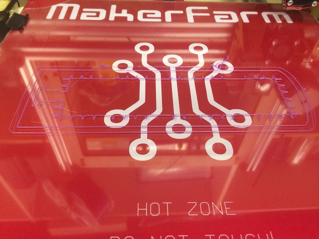
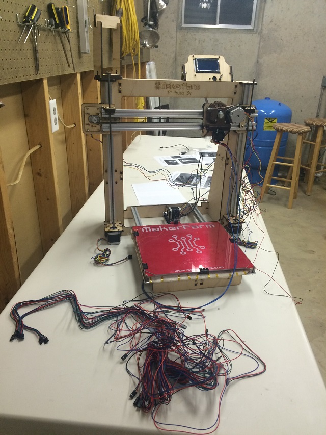
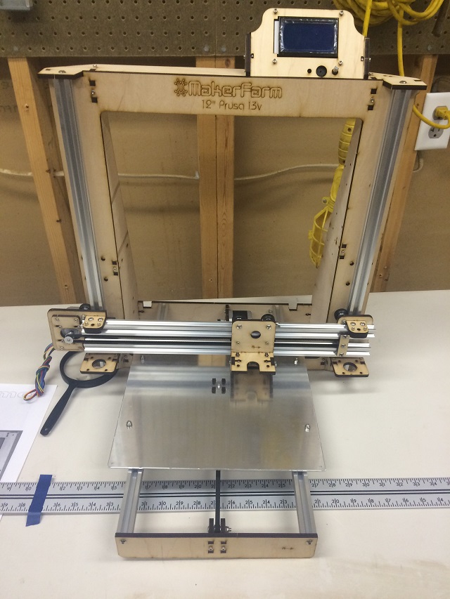
Well I get it that your frustrated, but let me show you this. This is a picture of my pond. It is iced over and covered in snow.

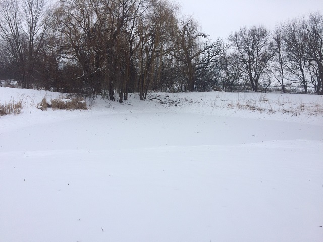
What you don’t see there is water. That is important you see snow and ice. What is never visible is there are two things called “diffusers” sitting 10′ below the surface doing nothing.

Why are those diffusers doing nothing? Because there is no wind. If there is no wind, then this windmill (we call him ol’ scrapie because I cut my leg building it) isn’t doing its job and pushing air into the diffusers.

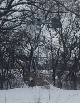
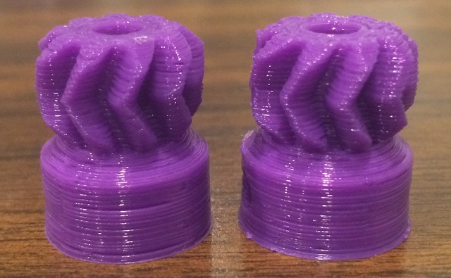
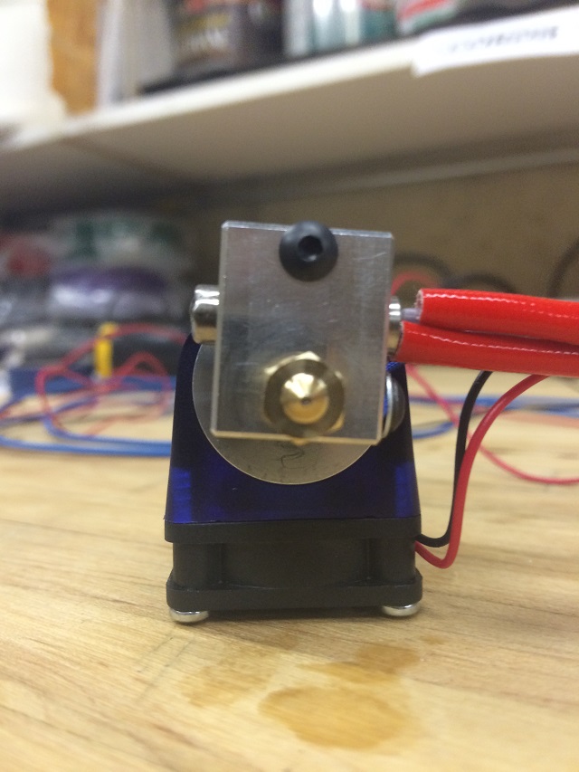
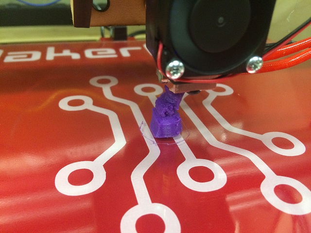
The windmill has an air pump in it directly attached to the propeller. When the wind blows air goes don’t through hoses that go 15′ into the pond and pushes that air into diffusers. Here is a pic of what it is supposed to be doing.


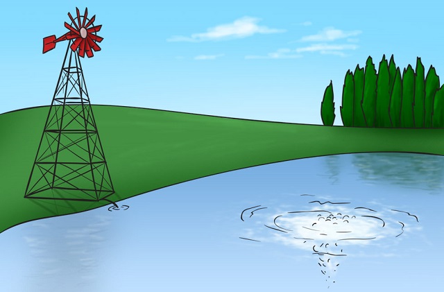
The diffusers is exactly the same thing as a bubbler in an aquarium, but instead of just oxygenating the water for a pond they serve one other very important purpose; they keep a hole in the ice to allow the contaminates of the fish waste to evaporate out into the atmosphere. Without those things this big giant bass is not going to survive the winter.


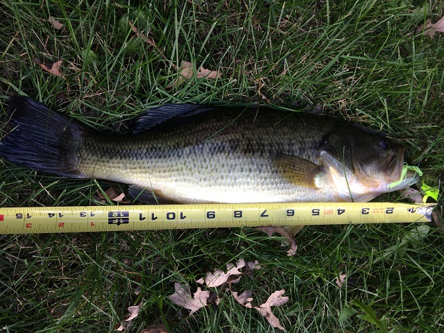
Here is what the bass is thinking now.


Well that is a tall order. I am no Trump, but I do know about ponds and also know how to listen to my wife, so here is what I did to solve both of these problems.

First I ordered one of these!!!!

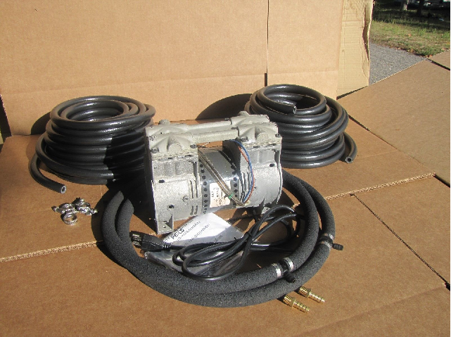
That is an air pump for a pond diffuser!!! I probably overpaid for it because in such a hurry to fix this problem. The plan is to set that bad boy up and bypass the windmill pump and save the big giant Trump supporting bass. Fish Lives Matter! My master plan is to set this up in my garage and just connect those hoses together all the way up to the windmill. Bypass it and get those diffusers going!!!


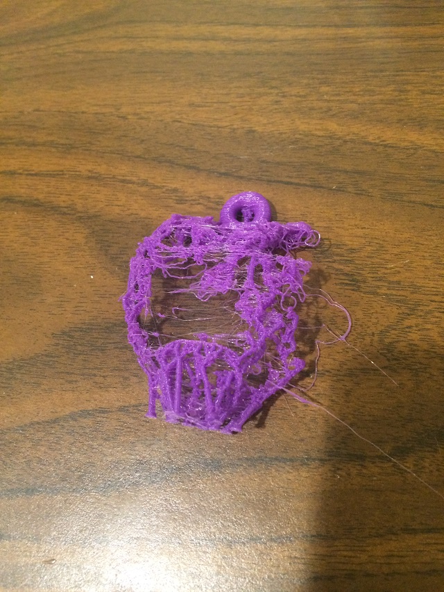
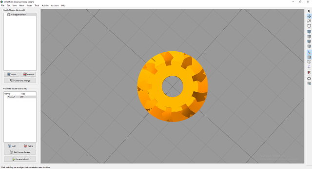
Then I ordered one of these!!!


Incidentally both cost almost the same amount of money.

Monday 12-19:

I have an interesting backstory on that diffuser I ordered for Rosie. A couple of weeks ago I came home from work. I enter through the basement where my office is and it was a very typical thing, I first dropped my nerd gear off on my shelf, then started to walk upstairs. As soon as I got about half way up the stairs I smelled something that just made me feel really really calm and comfortable. I was so taken aback because I don’t think my house every felt that comfortable. I asked Rosie what it was. And she told me it was some aroma therapy thing or something. I am actually pretty exited about her getting this going. I know some people have a knack for making their homes comfortable for their guests and children and that is what I want for my home.

Now enough about Rosie’s diffuser, let’s get back to talking about my pond difussers.

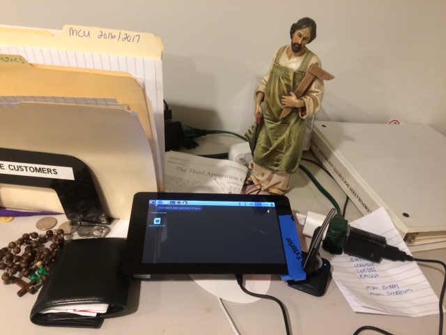
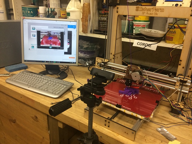
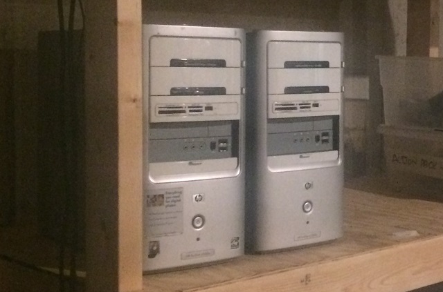
Since I started writing this post it had occurred to me that even if I do get the air pump and it does work as expected, it has been so cold it will take a long time, like many hours for the little bubbles to actually break through the ice and be visible on the surface. Wouldn’t it be neat if I could do one of those time lapse videos over a couple of days and show that at the end of this post? Yes, I agree that would be pretty neat. I have thought of ways to do it. My iphone has a time lapse setting on its camera, but I can’t responsibly do that. As important is this project is to me I can’t be away from my phone overnight like Obama and Hillary were during those 13 hours of Benghazi. I had to think of a better solution and guess what I have? All of this!


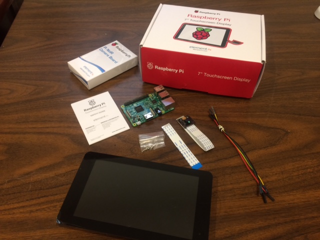
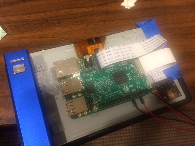
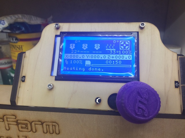
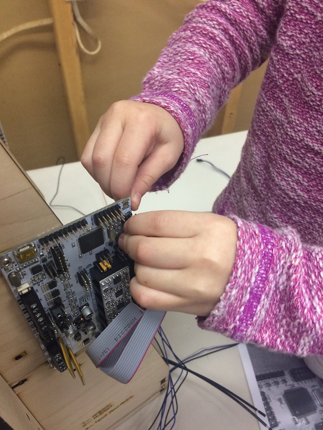
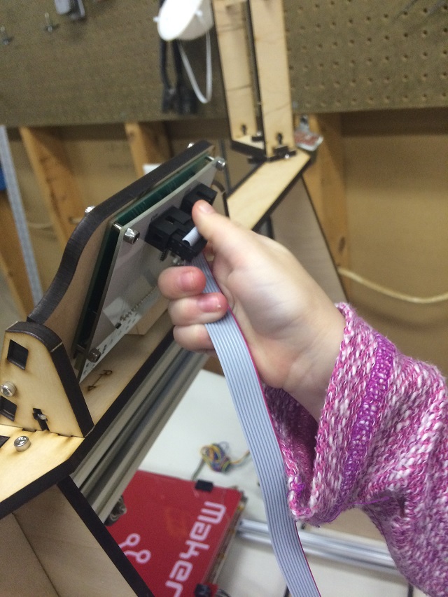
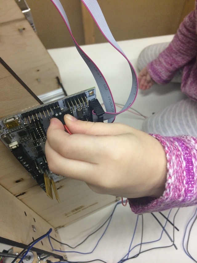
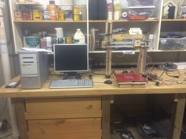
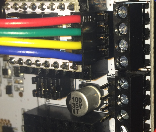
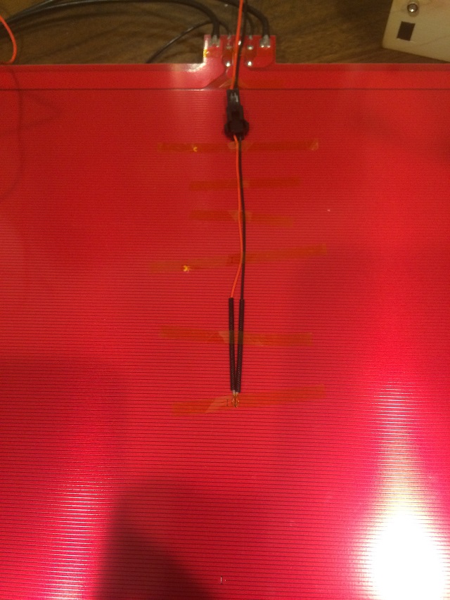
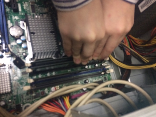
Now that is a picture of a Raspberry Pi computer, a screen and a little camera module called a “noIR”. Which means “No infrared light filter”. That means it can pick up very low light and hopefully even capture some video in the middle of the night.

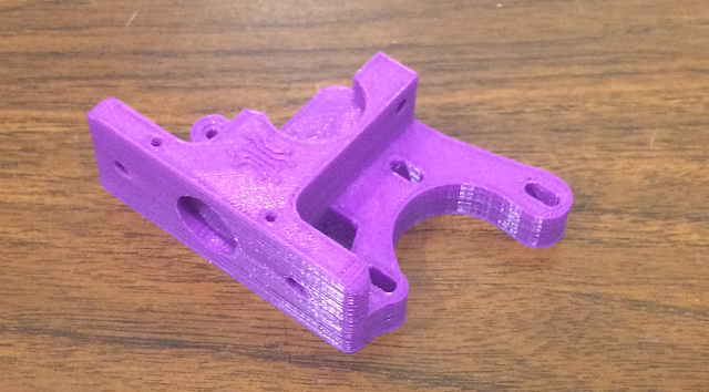
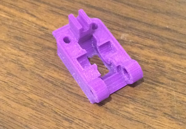
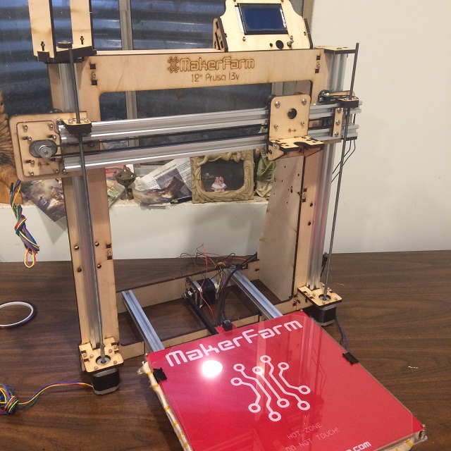
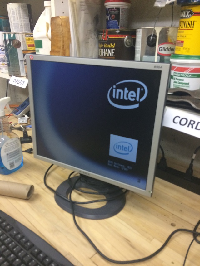
Here is a picture after I put it all together.

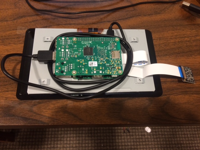
In the picture above the camera is actually folded over to the right lense toward the table, but it does work. I installed software on it that would allow me to view it’s screen remotely. I will have to figure out how to make that work later.

Tues 12-20:

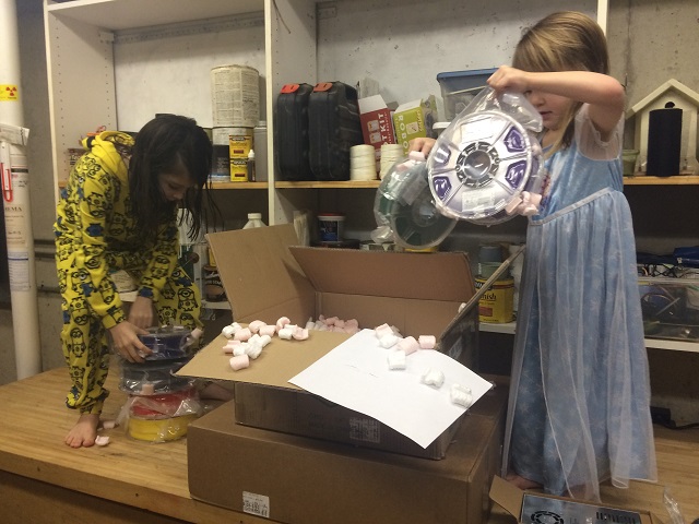
Guess what arrived today!

This!


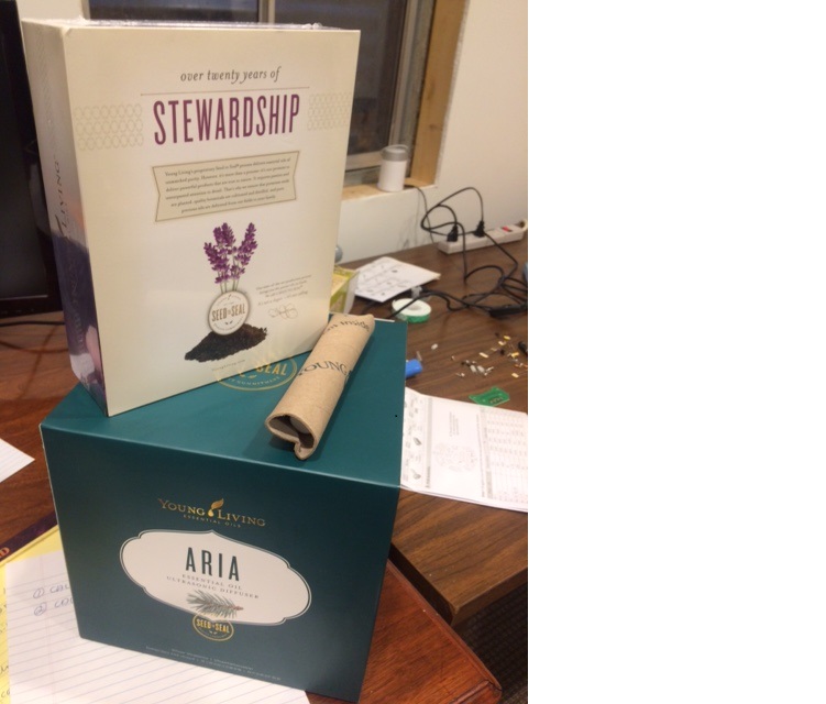
That is Rosie’s diffuser! Nice. Now I don’t know anything about how that works but I am glad it is here. Guess what came later?
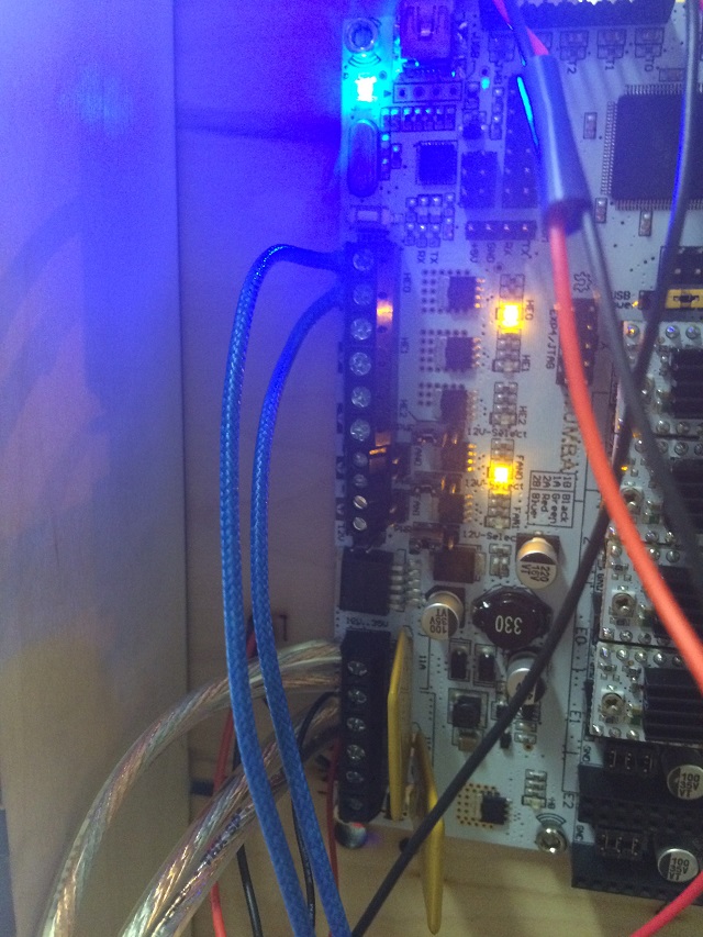
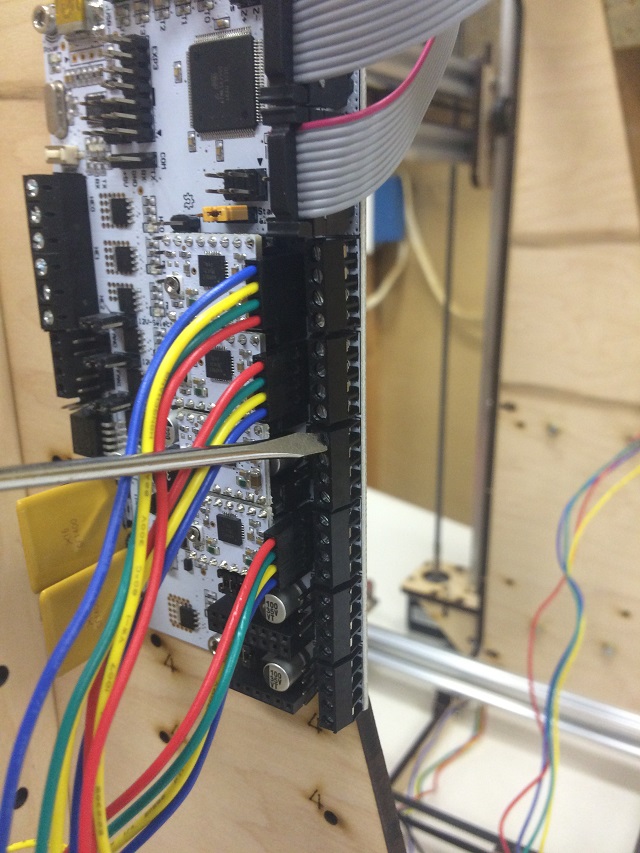
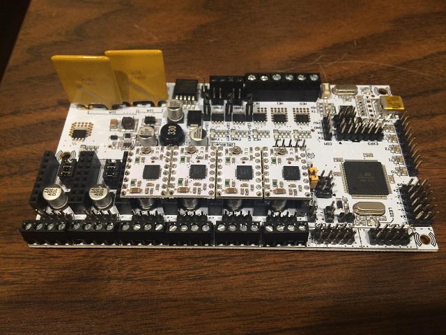
This!


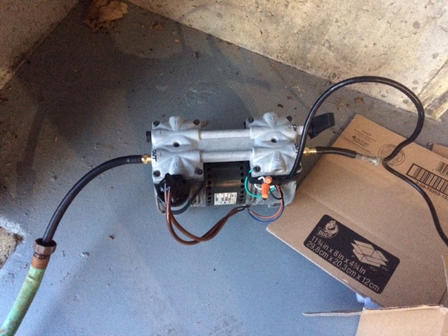
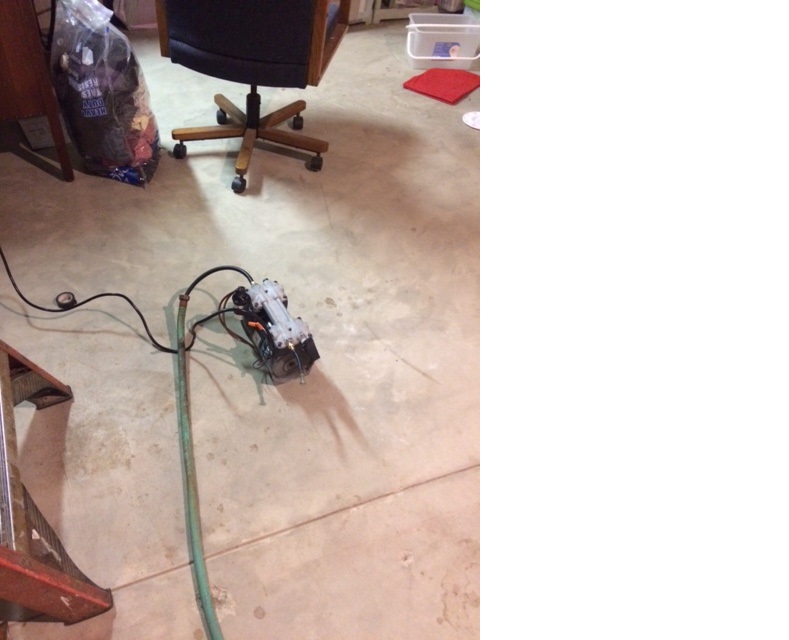
I got too excited and never took a picture of it as it was in the box, that picture is after I got it all put together and plugged it in (I was so excited I forgot all about documenting it).

Now it is a long long long distance to Old Scrapie. Old scrapie is the windmill if you don’t remember. It is the thing that is supposed to be pusing air into the diffusers that are already in the pond. It isn’t working because there is no wind. My biggest worry now is the distance. The new air pump came with these:


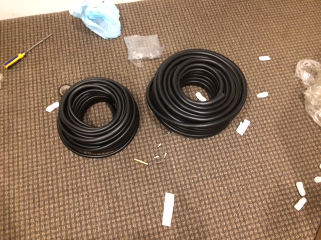
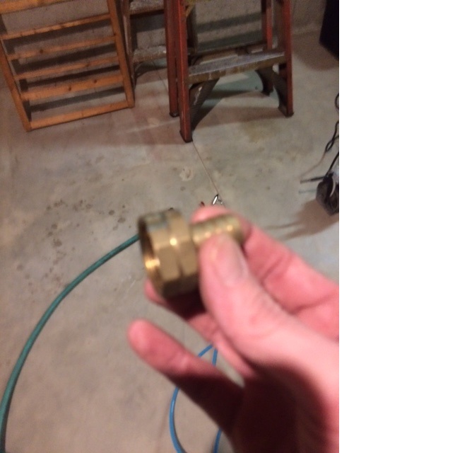
That is 200 feet of air hose. And I notice right away there is only one of these.

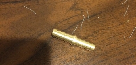
That is a coupler. 200 feet of hose won’t be enough and that coupler would only connect those two hoses together. I have to figure out what to do. I do have a garden hose that is about 100 feet and that should do the trick. I finally find it, it is underneath the front porch and it is frozen with all sorts of kinks in it.


It is clear to me there is ice in it. It is heavy very rigid and just getting it into the garage near where I am working was a difficult and annoying task. I bring it into the basement to thaw it out so I can get the ice out of it. I am not sure what to do.

After the hose sitting in the basement for a few hours I am getting too anxious and want to get the pump going. As I am figuring out how to connect it together without the proper fittings I start to get sad. If there is ice in this hose then I am sure there is ice in the hoses that go from Old Scrapie to the pond diffusers. I am totally starting to feel depressed right now because the last thing I want is to have me have bought all of this stuff and then have my fish die anyway. Uuugh… I can’t think about this now and must move ahead and decide to rope my kids to help me. I have to get the ice out of the hose before anything so I drag the air pump into the basement and connect one end of the hose to it.


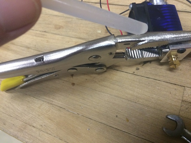
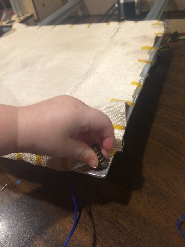
Then I get my most hard working kid (actually my only volunteer out of three kids) to hold the hose over a bucket at the other end.

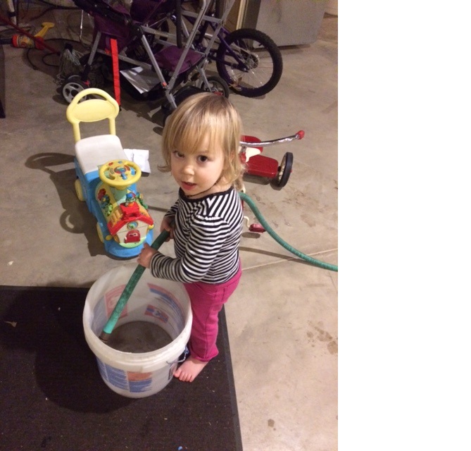
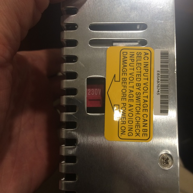
I turn on the pump and nothing happens. I am not one to give up so I think about it for a bit. If I want to move ice chunks out of that hose I just need more pressure. Simple problem to solve because I have ONE OF THESE!

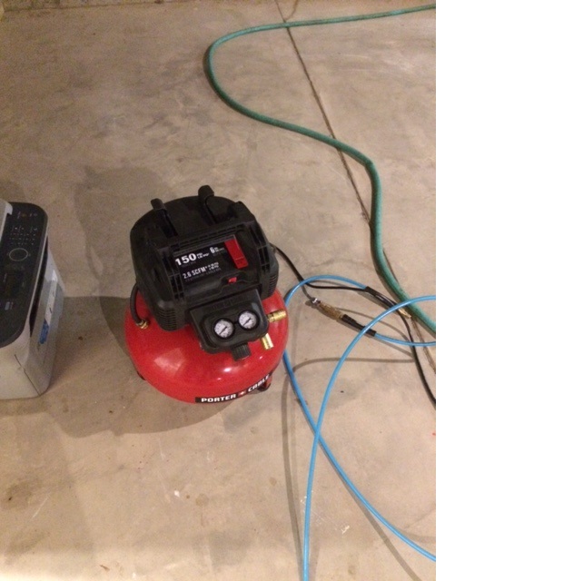
That is an air compressor. That 150 you see at the top means 150 PSI (Pounds per square inch of pressure). After a HUGE mess of water all over the basement floor because my 2 year old assistant wasn’t watching, the hose became cleaned out of ice and water quite quickly).

Now I still have the problem of getting the garden hose connected to the actual pond hose and the lack of connectors. Lucky for me I am a middle aged man and what that means is I pretty much have something in some box somewhere that can help me solve almost any problem. I find a pair of these!


That is a brass fitting to repair the end of a hose when bad things happen to them like getting run over by a car and bends them so they no longer work (something that happens around these parts often).

And look at what else I found.


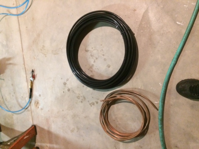
That is extra hose and copper tubing that I can cut and create my own couplers that will fit and connect right to each hose (I don’t know why I have that copper tubing, I don’t remember where I got it from or what it is for, but it is the exact diameter I need, let’s call that a Christmas miracle!).

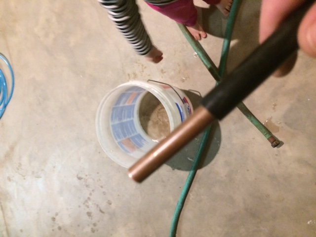
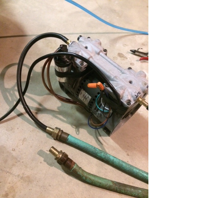
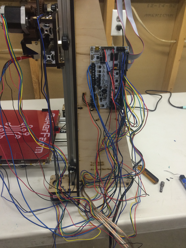
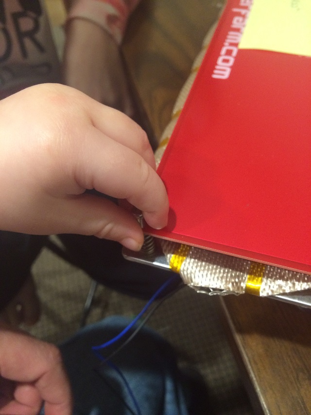
This is what our now ice free hose looks like hooked up to the air pump.

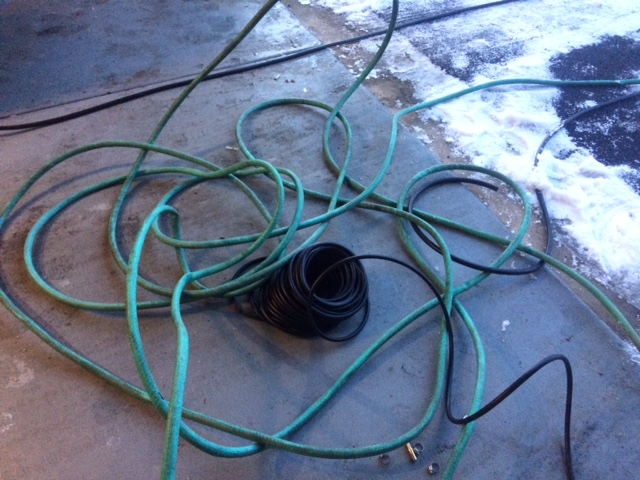
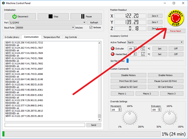
Now at this point I am way too excited I have to go outside and get this all connected. It is dark, my wife and kids are driving around looking at Christmas lights so I get hustling. First I have to show you a picture from the morning because it was too dark when I connected everything. This gives an idea of how far I had to go with the air hoses.

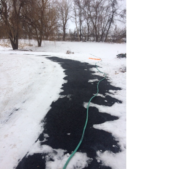
That is garden hose connected to air hose, connected to another air hose around that far tree going off (you can barely see it) to the left and all the way to the windmill, which is about 300 feet total) and then finally bypassing Old Scrapie to connect directly to the deffusers. Sadly once it was all done and this picture is late at night I can see the pressure that there is just a buildup of air. This picture tells me the air pump is getting to the fitting on the bypassed windmill to the diffusers going into the pond, but something is blocking the air flow… Probably ICE!

And that is where I am  right now. It is super cold out. I am pretty sure ice is in the air hoses that go to the diffusers that are already in the pond. I am not sure what to do and have to think about it. One way or another I will get it done. I don’t care if I have to go out and take a pick ax to the the pond and break a hole in it to sink a diffuser into it. Hopefully I can figure out a way to get the ones that are already in there going. It is supposed to warm up a bit over the next couple of days, perhaps that will do the trick to get them going.
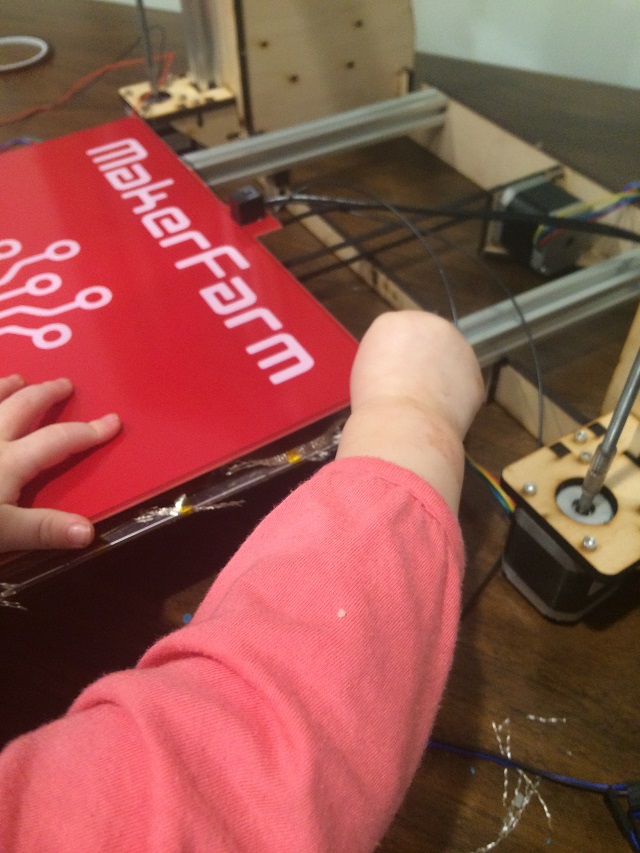
Sat 12-24:

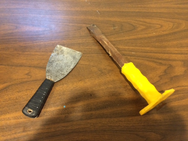
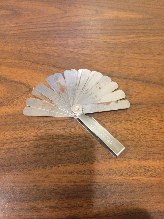
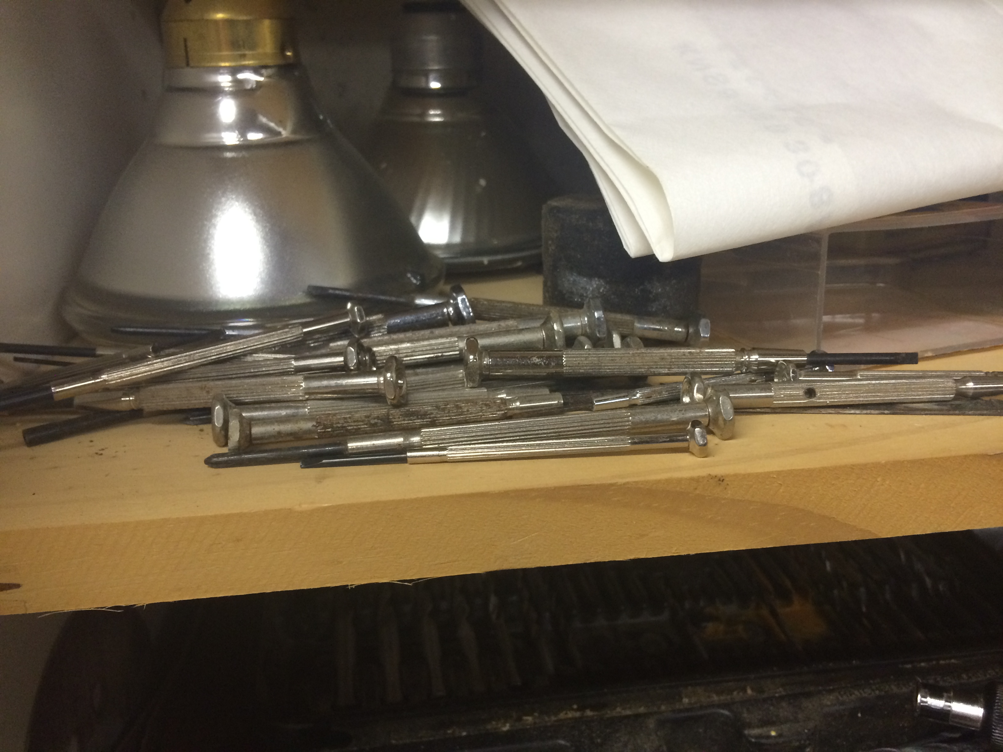
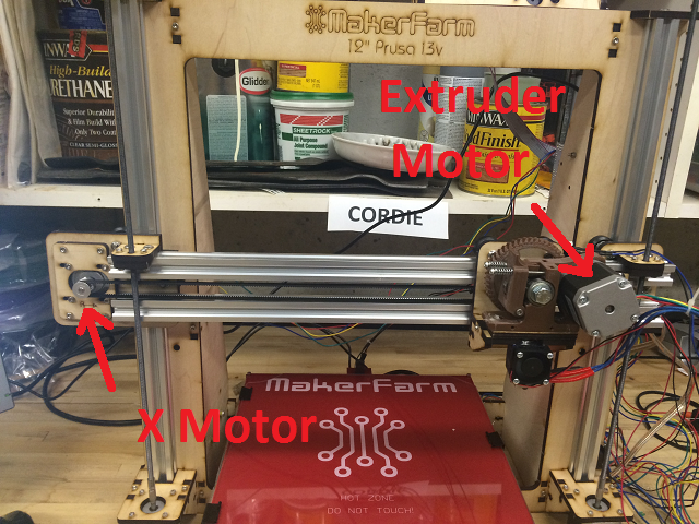
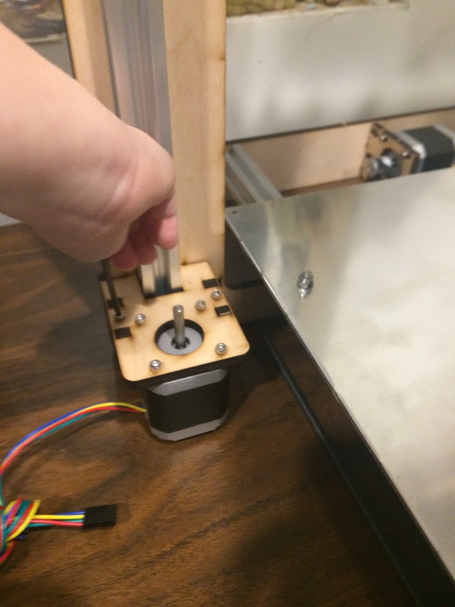
It is Christmas Eve and I only have a short time, but I don’t have to work at my normal job today so I want to really get things rolling with this. My goal is to get the ice thawed out and get air moving through to save my big giant bass and make the pond great again. I know those lines are frozen with water and my hope is that the only frozen part is the area where the actual air hoses go into the pond. If I can expose those and get them warmed up enough the air pump will actually do what it is supposed to and start those diffusers. I think big and look for my pick axe but I can’t find it. From what I remember the hoses are only a few inches deep so I grab these simple tools and head out to to the pond.

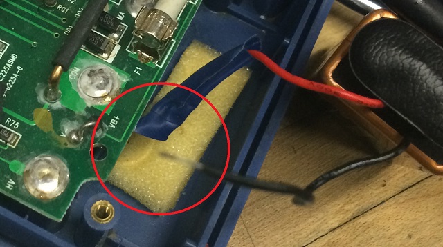
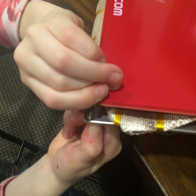
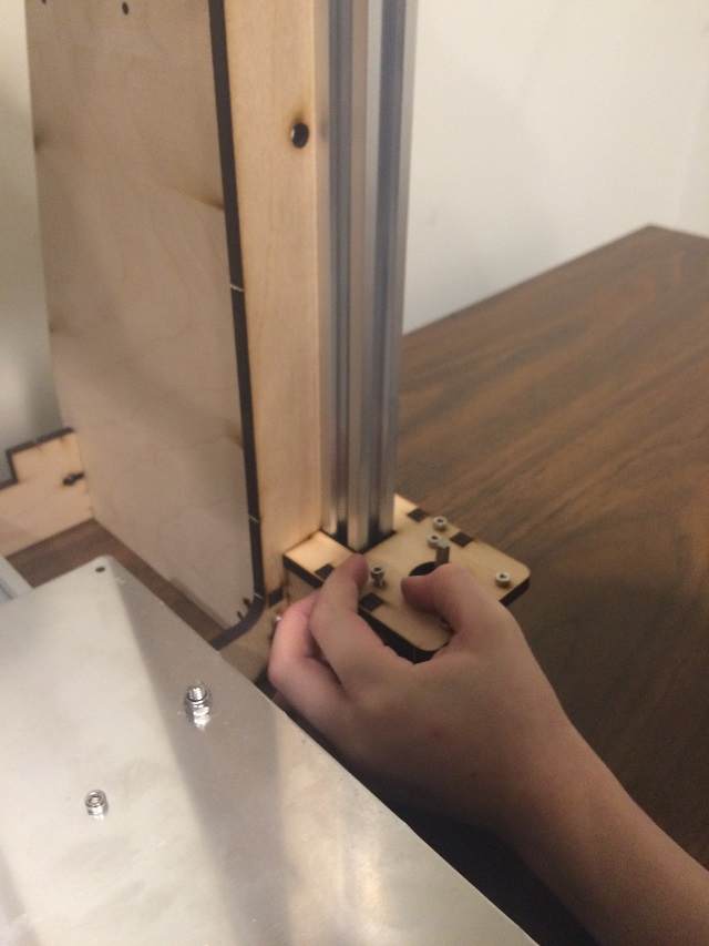
I slug away and my neighbor Rob helps. Eventually we find the hoses as they enter the pond (Rob actually ended up finding them because he does this kind of stuff for a living).

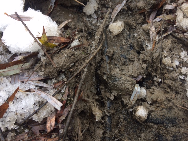
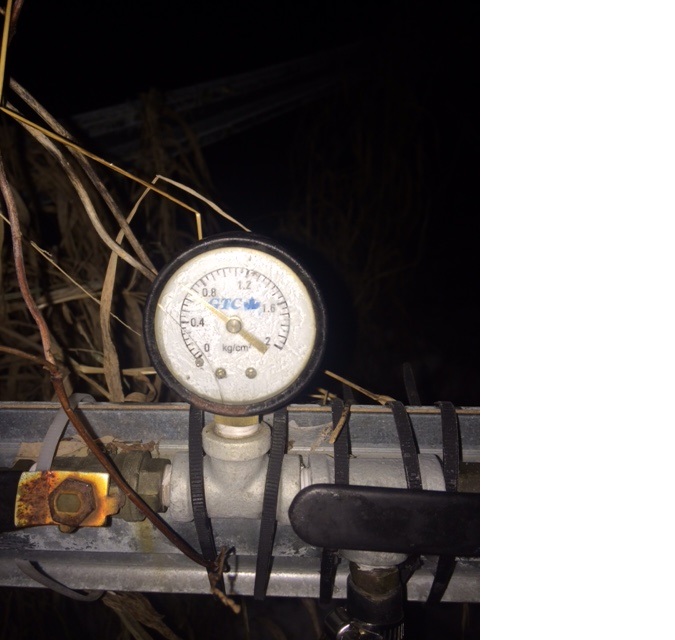
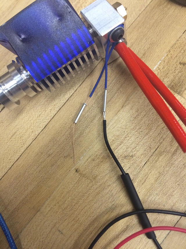
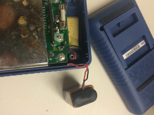
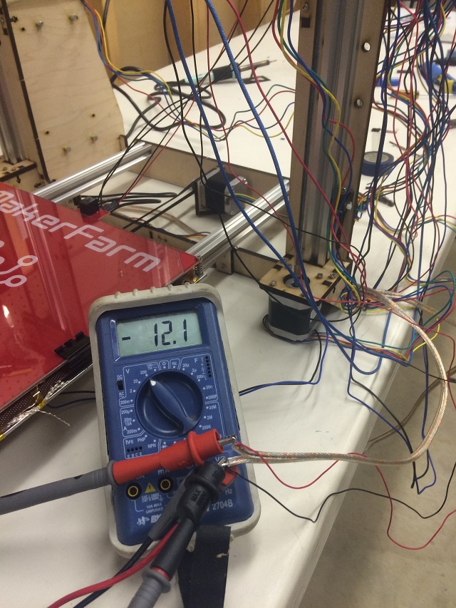
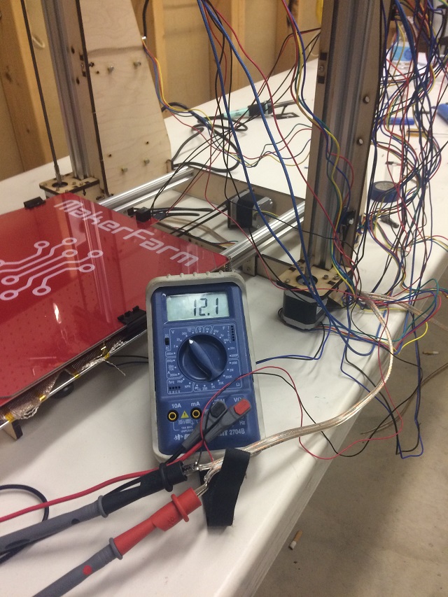
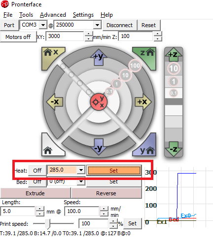
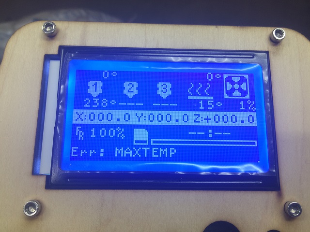
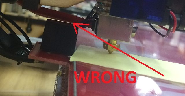
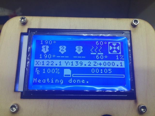
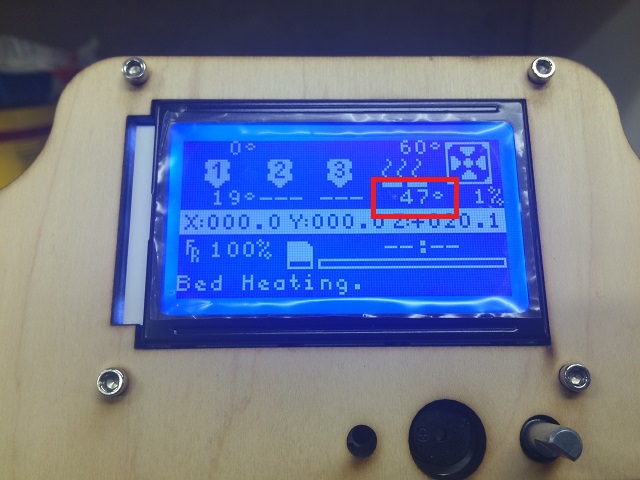
It is hard to see, but that is an exposed air hose in clay that leads right into the pond. It is beneath the frost line, so we decide to just turn on the air pump. Perhaps we will get lucky. I turn on the air pump. The only way I can tell if air is actually getting down into the diffusers is if there is a pressure difference when I open and close the valves that lead to it on the windmill. Here is the pressure that is going through the hoses when both diffusers are turned on


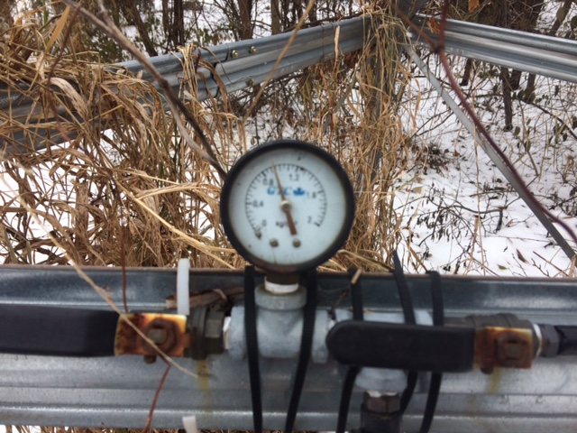
And her it is when both are turned off.

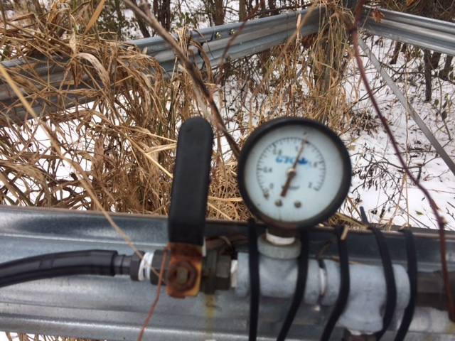
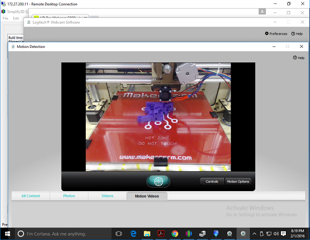
This tells me that air is actually going down into the pond and lowering the pressure. Granted it isn’t much air, but it tells me at least something is happening. My hope is that pressure will drop over time as gook and ice gets pushed out of the diffusers. I will check on that later. But NOW I have something I am really really excited about. I want  to do a time lapse recording of the surface of the pond! Remember this?

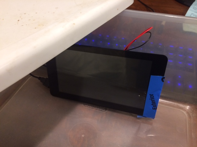
Yes… that is my Raspberry Pi camera setup. Now I put this into a box a few days ago to make sure it didn’t get ruined. I installed all sorts of software on it, camera software that allows me to connect to it with a web browser and take time lapse video. I pull it out of the box and this is what I see.


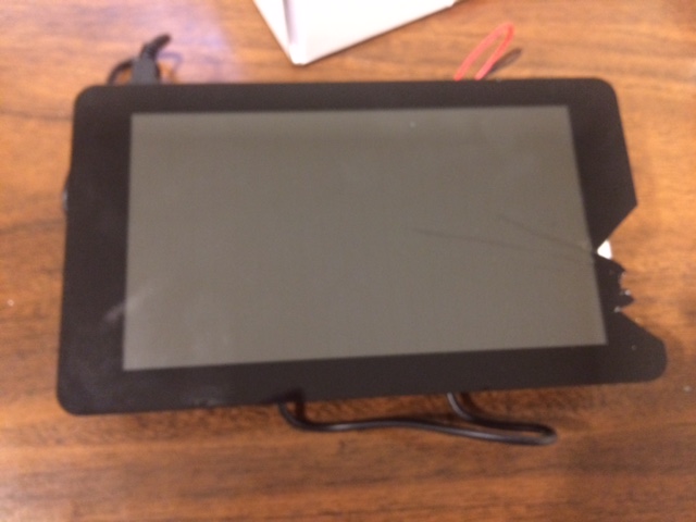
Yep… It is cracked. I am totally not sure how that happened, but I am focused. All I need that screen to do is still work cracks and all. The first thing I do is put some blue painters tape over it to make sure I don’t cut myself working with it. This actually makes me pretty upset. I really liked that little setup and now it looks like junk, but I have to focus on the bass that wants to make America Great Again, who know he may actually get to help by becoming our lunch someday.

We have all seen smartphones with cracked screens that still work. This screen is no different. It is broken, but working (Is that a thing? broken but still working). I have to check if the camera still works.

Blurry because of my iphone camera, but it works as well as I need it to. That is a close up of the screen showing the camera working. The next thing I need to do is weatherproof the thing. It is getting late and my family has to go to my mothers house in an hour or so so I put on a full court press. I grab one of those plastic bins you can get for storage, a small one with a top. I check to see if the camera setup will actually fit in it.

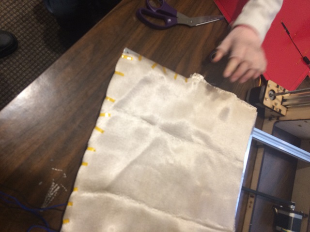
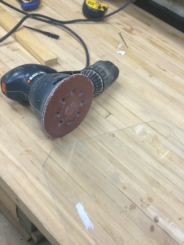
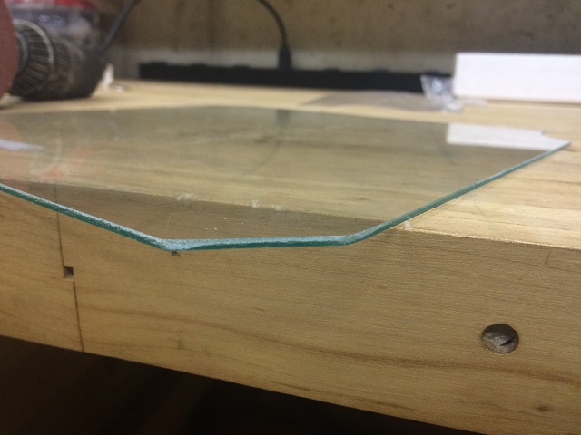
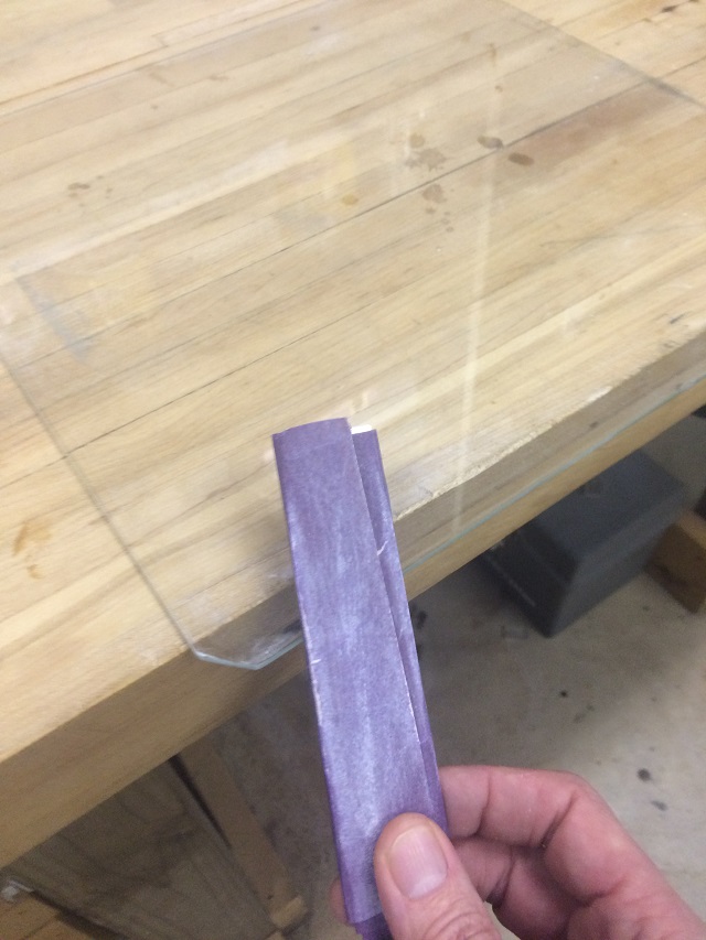
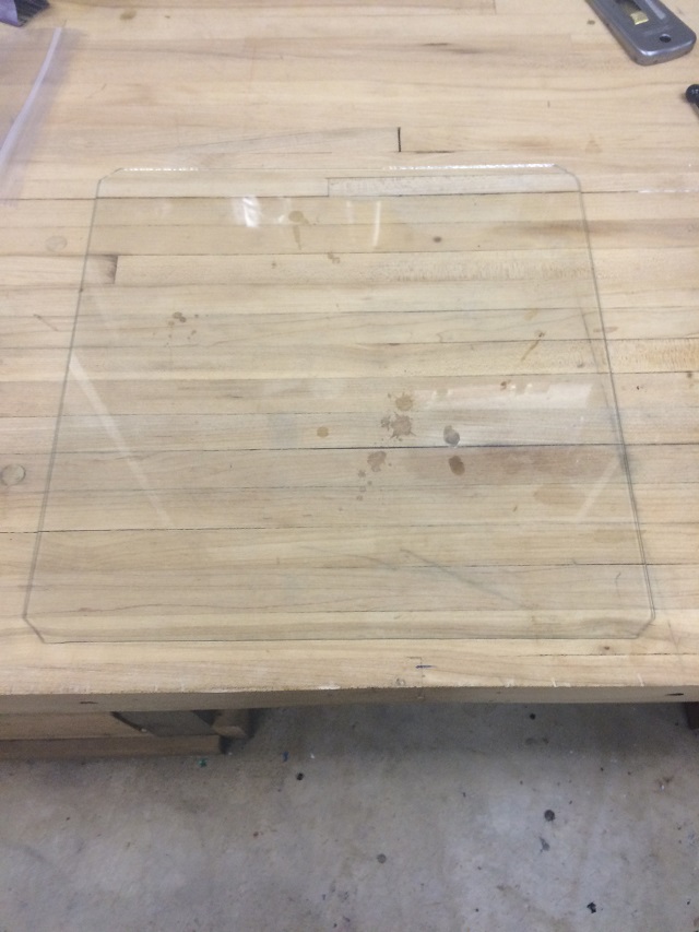
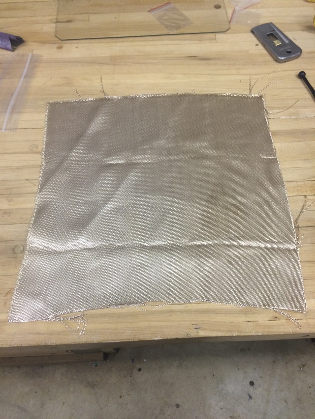
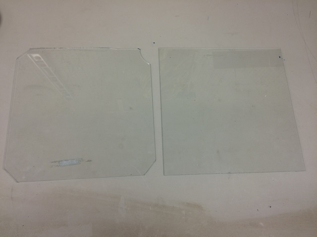
It fits. The box itself is translucent, I need a window. I have some of this!

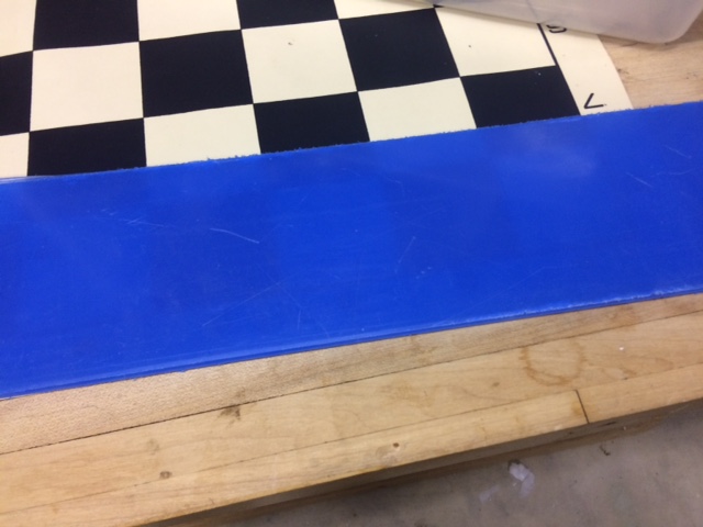
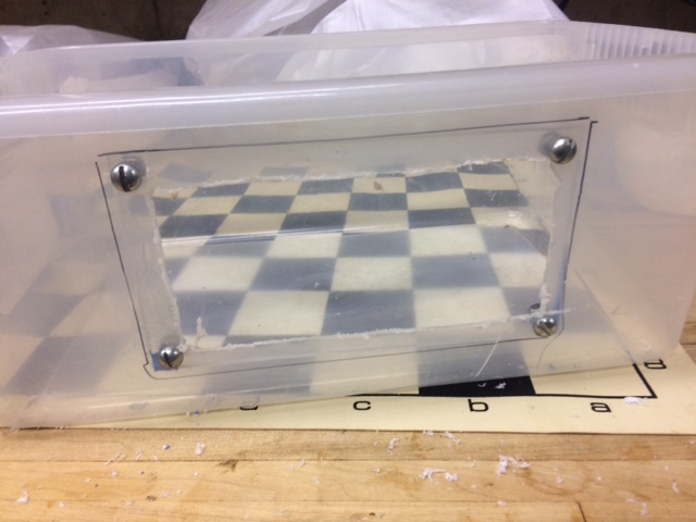
That is a clear piece of Plexiglas with blue film to protect the finish. I want to cut a hole in the side and glue it, but totally didn’t have enough time for glue, so I drilled holes and ended up with this.

I am running out of time so I grab all of the stuff, the camera and everything and haul it out as close to the pond as I can get with the extension cord I have. I setup a chair in the snow to put the box and camera on and start getting it set up and then guess what happens? Yep… I move the chair and the cover wasn’t on my protective box so my cool setup fell flat into the snow. When that happened I knew exactly how this kid felt.

I was at least as upset as the kid in the video. I didn’t even stop to take a picture of it in the snow. Here is what it looked like after I brought it in the house trying to figure out what to do.

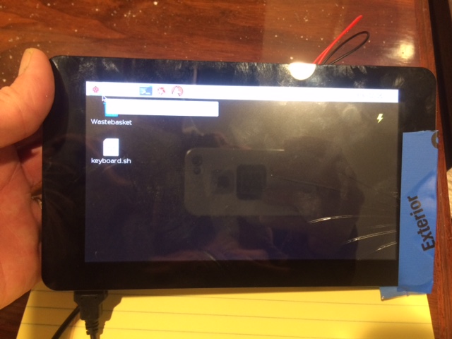
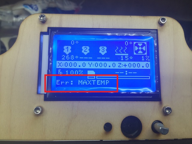
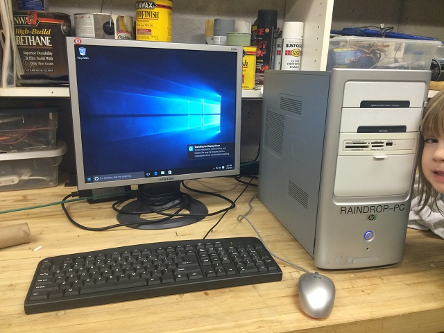
See the snow? Fuuuuuddddddddddddggggggggggeeeeeeee! I have no idea what to do. I first try to blow it off with my cool air compressor. I get it as dry as I can. I bring it up to the nearest outlet I could find and boot it up.

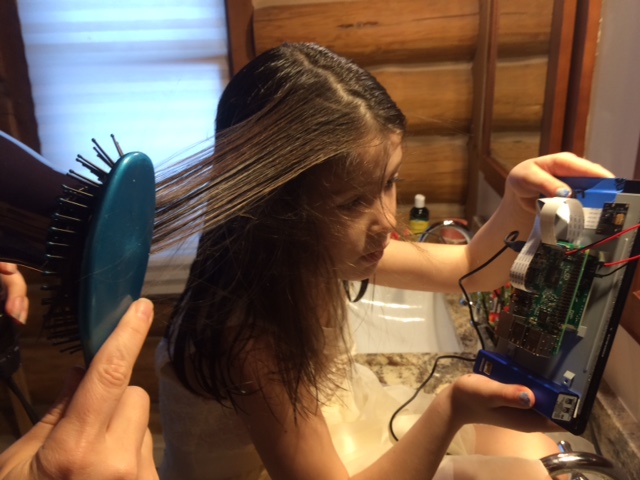
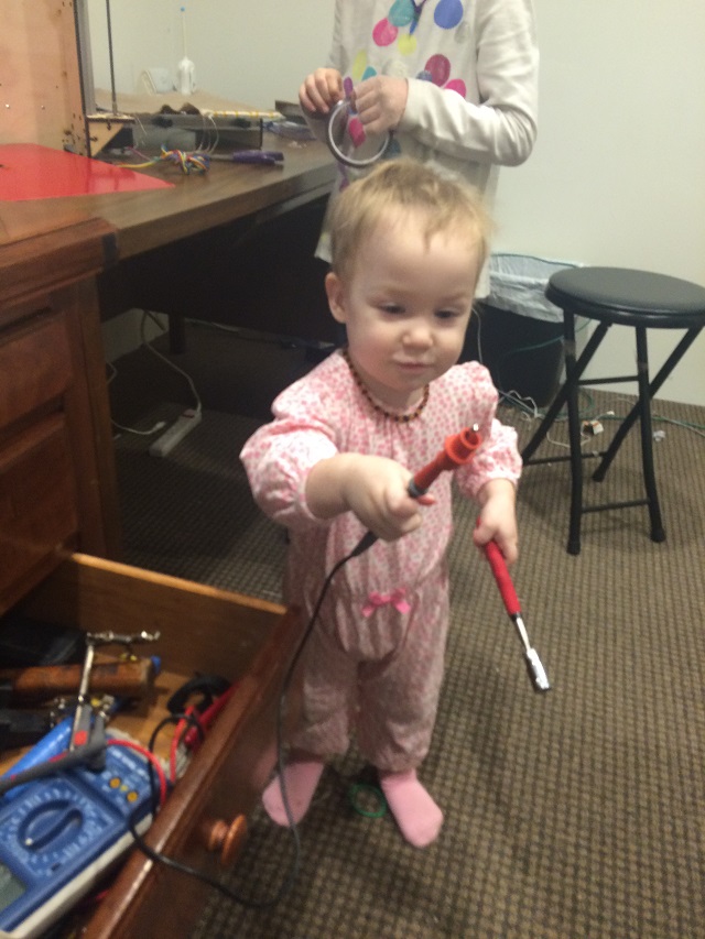
It works!!!! But sadly when I bring it out the pond to actually do its job, it just restarts itself over and over and over and doesn’t stop. Clearly it isn’t dry enough. Now I am totally running out of time. We have Christmas Eve dinner at my moms house and everyone is getting ready. I am a mess, I have been digging around in the pond and sloshing snow into the basement and my office. I am a mess, but I need something to dry this off so I can get my time lapse video. I think of something, I need a hair dryer! I find the only one in the house and guess what? It is being used because I have a wife and three girls and if there is anything that is going to be unavailable when we are about to get out the door it will be a hair dryer.

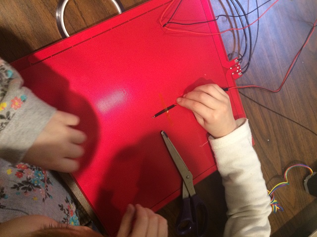
In the picture you will see below this is precisely how to solve a problem. My oldest daughter Hannah has a ton of thick hair, I know if I have to wait for that mop to get dried the schedule will be blown and we won’t get to my mom’s house on time. I know this because I dried her hair once. I did it only once because it take flipping FOREVER. So I hand her the camera and tell her to hold it in front of her hair to get it all dried out along with her hair. That should do the trick!

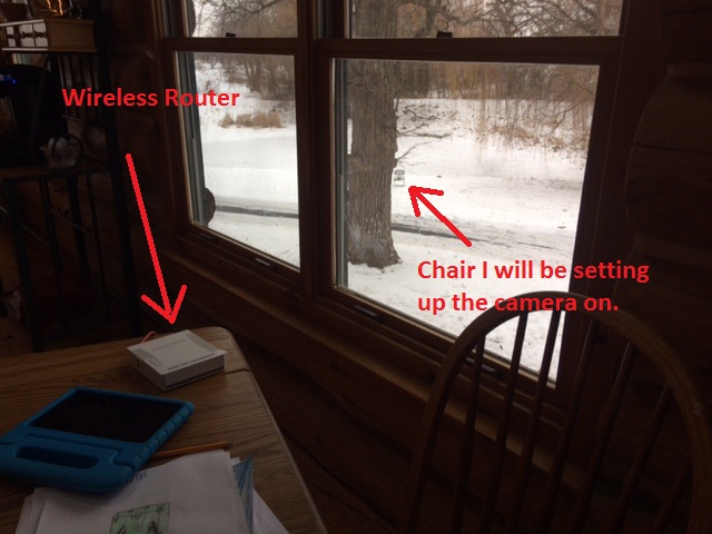
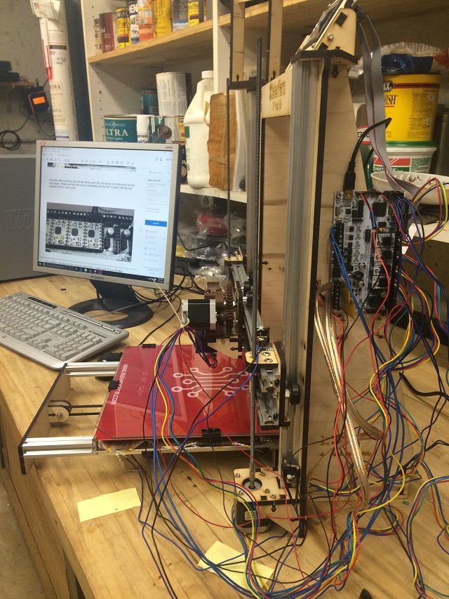
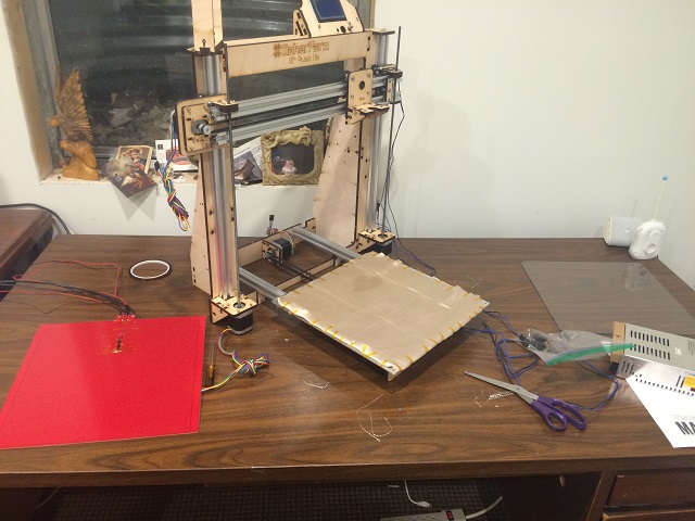
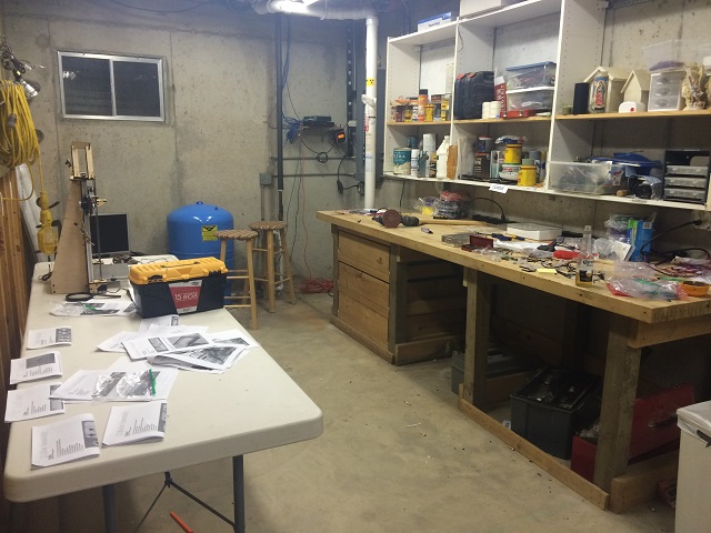
While that was going on I have other fish to fry. When I build the camera setup a few days ago, I connected it to my home wireless network. I tested that and it doesn’t reach the pond because it is too far. Here is a picture of where our wireless access point is ((The upper right on the top of the china cabinet).

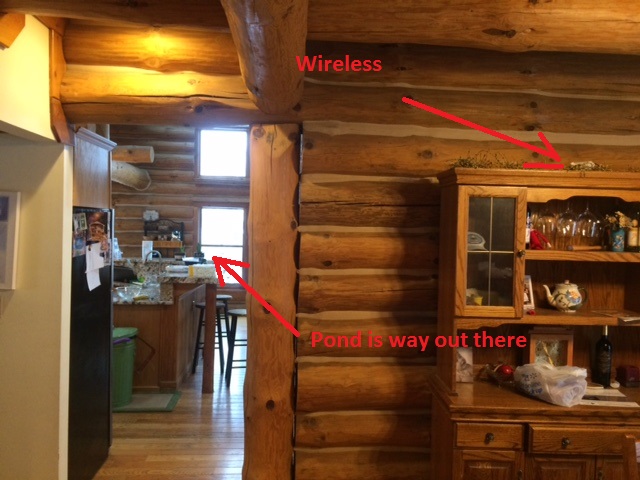
Out that far window is the pond by about 50 feet or so, I need to move that so I can connect to that camera if it actually still works. Here is a picture of me moving it with my 2 year old Kasia. She helped me bring it over by the window and set it up by a table.

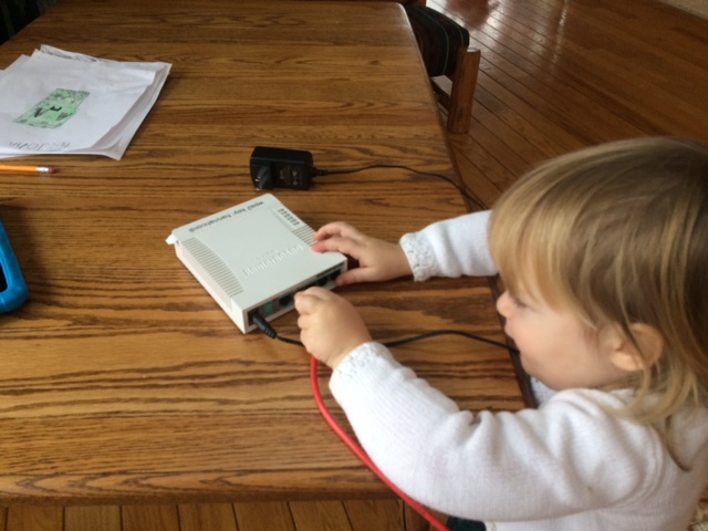
Here is what our wireless setup is now.

NOTE: MOVING THIS PROVED TO BE REALLY BAD… THE CABLE I LEFT ON THE FLOOR LEADING TO THE WINDOWS DESTROYED A VIOLIN (my Hannah tripped over it) AND MY NIECE TRIPPED OVER IT AND CUT HER KNEE (Stupid stupid Joe for not taping down that cable).

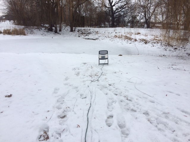
Finally Hannah’s hair is dry and so is my camera. As fast as I can I set it all up outside so it gets as clear a picture of where the diffusers will be bubbling up the oxegenating goodness. Here is the picture of the box and the camera, and the chair, and the extension cord and the snow that almost ruined my documentary.

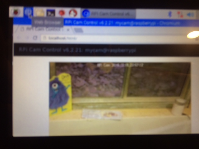
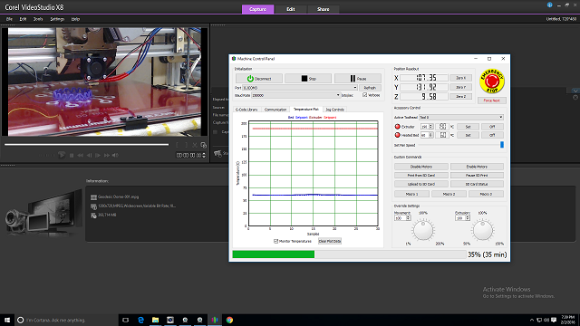
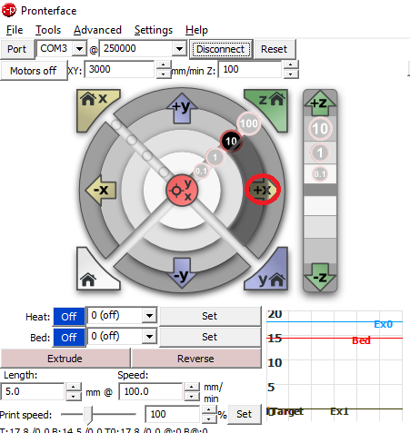
And if you were wondering, “why is it so important for Joe to make his time lapse camera connect to the network?”. It is so I can do this from my iphone at my parents house. I want to watch it real time. This is from my iphone connected to my home networks viewing my pond through the busted up camera over the internet.

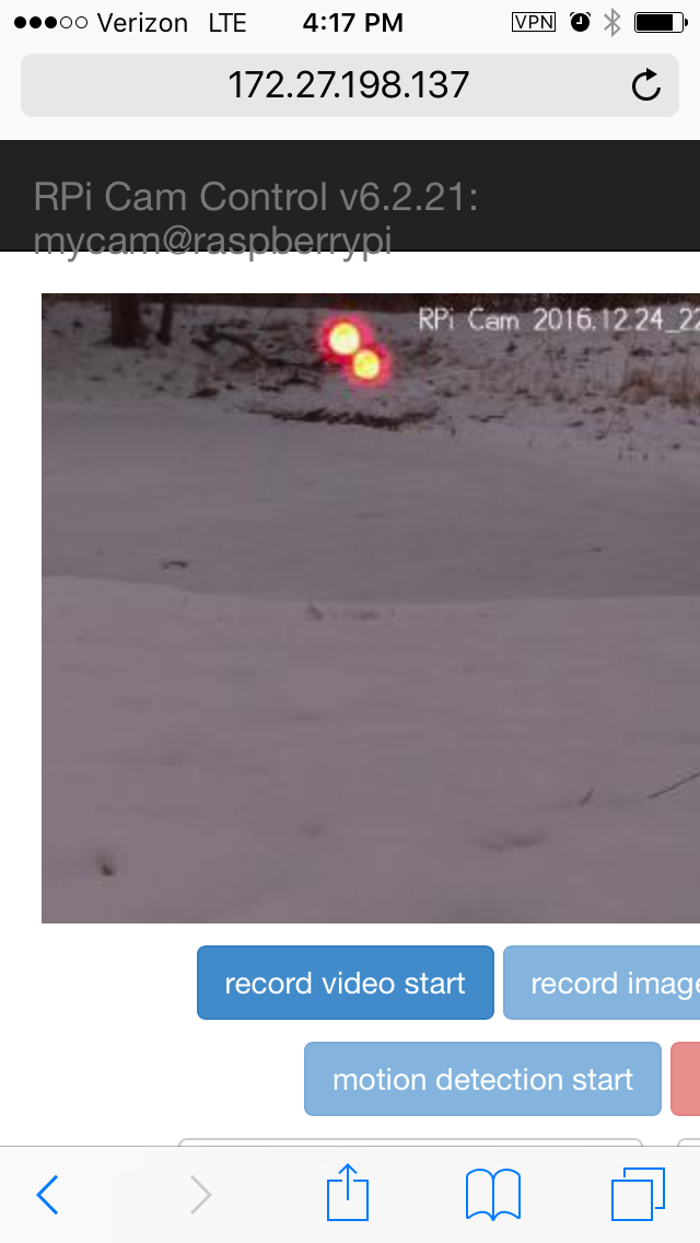
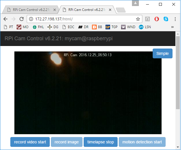
The lights you see there are a reflection of the LEDs on the Raspberry Pi computer board reflecting off of the plexiglass, my focus is on the pond surface. I want to see that break up over time in a video. That is the goal anyway. Here is a picture of the pond at 12:51AM on Christmas day. It is dark! I am not sure how this time lapse video will turn out. It may be a huge effort that amounts to nothing in the end. I guess we will have to see.

It’s Christmas!!!! The air pump has been going for about 24 hours now and the pond still looks pretty much the same. We are supposed to be getting a pretty big warm up tomorrow. I guess I will just have to wait and see.

12/25: It is late. All of my relatives have left and I can’t help myself. I have to mess with my time-lapse video. Figuring out how to make an actual video out of it took some work. As I was messing with it there were lots of things that went wrong. My timelapse camera ran out of disk space. I though the little card in it would be able to do a timelapse and it just didn’t work that way. Apparently the timelapse feature just takes a picture ever few seconds and then saves it as an image file. That would have been fine if it were on an actual full blown computer, but that little PC only had a couple of GB of space. I did a lot to get this interesting timelapse footage.

That is a video of a muskrat walking across the edge of the pond.

01-07:

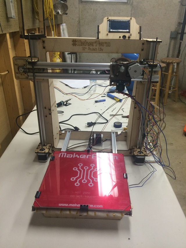
Wow… I blew it as far as timeliness. I wanted to wrap this up a week or so ago, but with the holidays then getting sick, and catching up on work, only now do I have a chance to finish this. It was a hard road and even after getting everything setup, there was some issues with leaks in the joints of my air hose and the pressure kept popping a couple of them apart, but after fussing with it…. I finally…. Have…. This!!!!


PROJECT RAINDROP – Charlie’s Tweaks

It has been a long fun journey putting this printer together and getting it printing. Where did we leave off from last post? Oh yeah… That is right… We need to get the girls plugged back into this. But before we do that my buddy Charlie has been giving me tips that he uses on his printer to get things running really smoothly and even improve the quality of his prints. Let’s take a few minutes to apply what I call “Charlie’s Tweaks” to our print environment.

First of all, I recall Charlie sending me a PDF with some settings. I am going to look at that first. It is called “My Settings” and it is all his finely tuned adjustments. I open that PDF up and apply all his settings to my printer.

my settings

The next thing Charlie said is that he thinks my heat bed is just a hair too low. I suspected something like this when he told me a week or so ago that his leveling process takes 25 minutes… Mine only takes about 10. Here is what he said:

Here is my thought of why the prints look rough.   I can clearly see the rows,  even though you can’t get rid of them totally,  you can reduce them to see a smoother surface. try raising the bed just a hair.   each row should be pressed into the previous row. here is a cross cut of what i mean.  the line is the bed, and the left circles are how I think the filament is being laid down.  the right side shows the filament being pressed into the previous layer.

FYI,  If I watch my printer in action,  I cannot see the filament being laid onto the previous layer,  it looks like it’s just riding on the previous layer.

And he sent this image to help me understand the physics behind what is going on with my print resolution.

what i think is happening

Like a good student I am going to repeat it back in my own words. I need to lift that heat bed up to as close as possible to the print head. What that will do is allow layer after layer to be more compacted against each other making the print look more smooth. In another email he said my nozzle temp should be 215… I am at 190. So I set that too.

Lastly,  the temps I print pla at…bed … 70 degrees,   Nozzle…215.  I do not bother with the preheats,  I just start the print job and run.

He said it takes him 25 minutes to level the print bed and it takes me 10… I am doing something wrong. He sent me a file to print out the first layer so he can very precisely adjust the height of the headtbed.

Now I tried using paper to adjust the height of that bed, but now that I realize how absolutely critical that part is… I am going to use one of these!

IMG_2547

I bought that last summer when a rocker arm on one of my lawnmower engine cylinders popped off the cam shaft. I will now use it for this! Oh… And that is called a “feeler gauge”. It is designed for very accurately measuring distances between two things… thinks like rocker arms and cam shafts and also 3D printer extruders and heat beds.

OK… Well I check it and I can’t even slide the thinnest blade between the glass and the print head. I suspect something is up… There is NO WAY I could have been that precise. I try the other paper I used that used to fit… Sure enough it doesn’t fit. I try to clean away any material on the end of the head and it still doesn’t fit. So I have to call my wife.

I know what you are thinking, your are thinking, “Why does Joe have to call his wife, she doesn’t care about his projects, even though she is super smart and pretty.” You are right to think that, but I do need my wife’s help because she knows where the acetone is… I need that to clean off that print nozzle. I call her up and when I said “acetone” she said, “WHAT?” then I said “Nail Polish Remover” and she told me where to look.

Acetone and myself got very far back. I have 4 sisters. One of them (or maybe it was more than one) destroyed a very nice pool table for kids my God Father got me for Christmas one year. As a result I am not very good at any sport that requires hitting an object with any other object that is not actually flat. Things like pool and golf I am not good at. Ping pong I am fine. I blame by sisters and I blame acetone.

I clean off the head with nail polish remover and try again. Neither the paper or the feeler gauge can get under it. I figure I must have bumped something and then just re-level the whole thing at .0015 inches. That is 15 thousands of an inch. The thinnest gauge on the tool.

I must say using the feeler gauge instead of the paper is way easier. I have more confidence in my leveling job. I don’t know however if that is what people use. Maybe 15 thousandths of an inch is too far away, maybe it is too close. Let’s find out. Charlie sent me a printer file that he uses to test his leveling job. He said this:

If I see any of the little squares not the right shape or distorted or missing(bed too close).  then i adjust the bed,  scrape off the test layer, and do it again. If it prints out perfect,  bed level.

It works for me.

Let’s do this all Charlie’s way (He didn’t tell me to use a feeler gauge, that is on me if this doesn’t work out).

No video this time, that is for later. I am just going to print that first layer and take a picture.

Here is a summary of what has changed since last print:

  1. Heater Bed Heat bumped up from 60 degrees Celsius to 70.
  2. Extruder Heat bumped up from 190 degrees Celsius to 215.
  3. Adjusted the bed to .0015 inches (This was my idea and may be a mistake).

I press print and will stop it after the first layer.

IMG_2549

Now i know that is not right, that first layer is supposed to be closer than that. I use the feeler gauge again, but instead of having it be able to slide beneath the print head and glass where I can barely feel friction, I redo it the way I did it with paper. Where I get it underneath the print head first and then feel a little drag coming out.

I didn’t grab a picture that time because there were little imperfections and was going to read up on it an do it one more time. Since reading up on it I decided it will be good enough to go as is to see if the other settings help my print quality.

So I print up another copy of the smallest thing so far. That first print… The Little Gear. Here it is in super fast motion. This video is only 3 minutes.


While the little gear was printing, I had the girls come downstairs and asked them, before seeing the printer do its thing and asked them, “What do you think it does?”. Here is what they said. It is only 1 minute.


After that I took them into my office and I told them I wanted to show them this website that had Valentine stuff on it. I said we should pick something. I took them to a website called Thingiverse. It is where people share 3D print files to be printed on a 3D printer.

They both went bananas when they saw this one:

I told them, “Yeah… We will get that”. And I sent them upstairs… They were still clueless and didn’t make the connection that this had anything to do with the printer.

The thing I have to figure out now is how am I going to get a light for that thing…. I have an idea…. Something they can build themselves.

OK… To win over my girls, I have to print one of those to make sure it turns out OK. I need to do this without them. It will take a long time, probably 4 hours for each side I am guessing.

Meanwhile, the little gear finishes and I set them up side by side to see if I can see any difference. Here is a real close up on them both. The one on the right is the new one.

IMG_2551

I am not sure if there is much of a difference. They both look pretty good to me at least at this angle. I am pretty sure I didn’t do something right. I have seen other prints that look better than that.

I am not sure what to do so I get back to my girls project. I load the heart up into the software and I must admit right away… I am not sure about this at all. It builds these little support columns to build up the heart shape (Those are meant to be broken off later). And I am not sure why this isn’t printed with its back facing the bed. It just seems like a strange way to print it.

heart-to-be-printed


I press print and go upstairs to watch TV. Note to self… I don’t think this thing will print… that doesn’t look like something for a novice. Hopefully “Charlie’s Tweaks” will make it fly.

I come back down when it is done. Here is what I see.

IMG_2552

Since it was easy… I tried turning back to my old settings heat bed 60, hot end 190 and it was so bad I just stopped it as it was turning into a way bigger mess than the first try.

IMG_2553

OK… I have a LOT of learning to do. Time for bed!

—————————————

I am really tired from not getting much sleep last night, but I can’t resist. I have to try to print something. I will pick something easy. I was asking my buddy Charlie about my printer missing a button for the control panel. He emailed me one.

JOEKNOB

Now that is a picture of it in a program called Blender. It looks like Charlie customized it for me… Oh… There is lots and lots to learn, this is so fun.

Here is printing that knob in super super fast motion (I ran it through the video program twice, so the clip is only 30 seconds).

And here it is installed.

IMG_2557


That was a great distraction and easy, but I am not sure what to do about that heart thing. I mess around with settings and there seems to be a pretty important option called, “Customize Support Structures”. Now that makes sense. I didn’t see how that heart would be able to print in that position. Standing up like that on with the tip to the board just looked impossible.

So I run the automatic support structure doodad and click print. Let’s see what happens. I record the whole process of course for the video because it is easy to do.


Now that is interesting and new. I am going to have to figure out how to break away all of those supports without damaging the heart itself. And of course there is this weirdo thing.


IMG_2560

I don’t know what that is… I am not sure how to clean it off. I grab a screwdriver and start chiseling away. I am not worried about the time it takes because in the future I expect I will have my kids doing this part. Here is what it looks like.

IMG_2562

I think it is super ugly. I don’t like it at all actually. But I am very happy…. Why? Because we can work with that. I am close… Here is how close we are:

  1. The kids chose the heart. Even if I don’t like it they were nuts about it. And now I have confidence that I can actually print it. That picture has some messy parts of it, but for a kid that will work. My goal of this whole project is to get something to trip in their brains saying, “Oh… If I think of something I want, I might be able to design it and print it at home!”. When I pulled out all of the stops and bought this printer that is what I was going for. I spent a lot of money on it (And a lot of time) and bought every single color they had… Not for me… But for them….
  2. The fact that the picture showed it was lit up is huge for me. That is right up my alley. 3D printing is new to me, but putting an actual “light” in something… It makes me super excited! That part is fun. I will have my kids build the “glowing part” of the “heart” they picked before they even see this thing. I taught them all about lighting things up before Christmas, It will be huge!

That is all for now… Stay tuned!


PROJECT RAINDROP – WE ARE UP AND RUNNING!

So after Charlie read my last post he gave me some advice. Turns out I didn’t level that heat bed enough. I went through the leveling process again using a thinner paper for the leveling. Then… Just like last time I hit “Print”. Check this out!

working1

Now that looks pretty good to me. It is about 1/4 the way done and as the computer program I used predicted it will take about 25 minutes.

It finishes that little gear and I pull it out.

IMG_2536

Then I print the next gear… This is fun!

IMG_2539

Then I print the bracket that holds the big gear. For that I took a little video of it doing its magic!

Now that is all fine and good, but we can improve on that last video. Just to print that graphic, it says it will take two hours. I need to do a couple of things.

Moving forward and I hope this wont be very time consuming for myself; my hope is that in the morning I can press print and then go to work. I want to make it so I can watch this thing from anywhere. More on that later.

Another thing I really want to do is to be able to speed up the process. Now I can’t do that for the printer, but I should be able to do that for the youtube videos. Wouldn’t you like to see a video of it printing an entire part in super fast motion? Yeah… I thought so… Let’s do that first. Plus I need something productive to do while that bracket finishes printing.

Last April I had to create a web commercial for my company. For that I had to buy some fancy video editing software. I download and install that on our RAINDROP-PC. I also attach a web cam to a tripod and point it at the printer bed. Here is what that setup looks like. See the webcam on a tripod and notice what our RAINDROP-PC has on the screen!

IMG_2540

Yep… The PC sees the video from the webcam. That is good. That means when I connect to it remotely… I see real time what is happening on the printing bed. Pretty neat, huh?

remote-view

Now I am just a simple few firewall rules from allowing me to connect to that machine from anywhere in the world to see and control my 3D printer. With that done… I notice the third in the series of 4 replacement parts has finished. It looks pretty good.


gear-bracket

That is so strange looking that purple bracket against that brown desk. It almost looks like I photoshoped it on top of the desk, but I didn’t. I just took the picture.

OK… Because I don’t want to be like the other two guys that have 3D printer; who will make fun of me when a part breaks for it that I could have printed out myself,  I print the last one. It is smaller than that that bracket so hopefully it doesn’t take too long.

This time… Because I have some time to kill, I setup my video software before printing and set it to record the entire print process. I will see later if I can take that video and make it play super high speed for youtube. Here is a screen shot of my “capture setup” in the video software. The piece is called “a guilder”.

guilder

I get the system all ready to print… Then I hit “print” on  printer, then wait until the heat bed heats all the way up and the hot end is almost up to temperature then I click “capture”  on the video software (I do this all from a remote connection to it to test my cool remote access to it for later when I am out of the house).

It says that will take 40 minutes. That is enough time to watch a show with my wife. Note to self… I started this at 9:07PM. I want to see if it really takes 40 minutes.

Note: I didn’t go upstairs right away because the printer just stopped for some reason during the print. There was a “force next” button on the software, so I pressed it, then it warned me that that was a “last resort” option only if I didn’t have any choice. I pressed it anyway and it started moving again. Not sure what that was all about. Also, with these three parts I have not cleaned the bed once. I think I am supposed to be cleaning the bed in between prints. Oh… Another funny thing… I keep forgetting that I can watch the printing process from my desk now with the camera I setup, but keep getting up to go in to the workshop to check on it…. Technically I can watch it from my iPhone now as I have an app for that.

——————

OK… I can’t show you the video. I went upstairs to watch TV with my beautiful wife. When I got back down stairs, the video was “corrupted and unreadable” At least that is the message I got. Now I remember having these issues when I was creating my web commercial. When I started the software for the video, I was asked to download an update to the video software and install it. My fault… I didn’t do it, so I messed up the video. Anyway… Here is a picture of my new part. Grrr… No video…

IMG_2542

So that is all the replacement parts I need for this printer. It was good practice. Now I actually get to print something that I want to print. Oooooh…. And I want to pick something that would make a good time lapse.

My father and I were talking about this the other day and I he got all interested in parts to build a geodesic dome. He wants to build a green house using the concept some day, so I think it would be a great visual for a video and also something to get my father to start reading my blog (My dad is just like my wife, he doesn’t like to read my blog… Weird, right? He is the smartest person I know, why wouldn’t he read his son’s blog? It is OK though… He is an excellent fisherman and really loves my mom, so I can forgive him.)

Let’s get to it… Here is what I am going to do… I am going to find a geodesic dome that someone designed already, download it to my printer. Setup the NOW updated software for my video camera… And I am going to figure out how to time lapse it so it looks really fun while printing in a video on youtube so no one gets bored!

For good measure… I reboot my RAINDROP-PC, then clean the heat bed and spray it down with hairspray to make it sticky.

Then it all falls apart… I can’t connect to it from my PC… It stops in the beginning of the print… I must have messed up something in the firewall rules when I tried to make it be available for me to connect from anywhere (Yes… I was showing off… I thought I wouldn’t be humilated when I said I coudl make it accessible from anywhere… It is good though… Good to have “my craft” bite me… Keeps me humble) As usual the part that I am “supposed to be good at” embarrasses me.

It was a good day though… It was a great printing day as far as I am concerned. Yesterday we had a totally bad part. In one day, I printed all of the replacement parts for the printer. It is midnight and I have to do serious work tomorrow… I will pick this all back up when that is over.

====================

OK… I had a long day at work, but am back at it.

I fix my firewall rules pretty quickly and now I can connect to it again. I try to print our geodesic dome and again… It heats up the heat bed and stops at heating up the hot end. It just stops. I unplug it and check the connections. I take them out and they look like they were in there perfectly fine. The heater for the hot end is the blue wires to the upper left.

IMG_2544

OK… So now I pull out my multimeter and guess what? It doesn’t turn on again! Remember last post I killed that red wire replacing the battery? I open it up and the black wire broke off the solder. I can’t get the board out to see where to solder it back in and I guess and connect it to the right place. In this picture the black wire is stripped, I did that before taking the picture.

IMG_2543

I get the multimeter all put back together and then start my print job again. This time it just starts heating up like normal. I start the video software to capture the entire print on video. When it is done I will see about fast motioning it.

Here is what I see on my screen when remoting to it. The upper left is the video stream. More toward the right is the printer control panel that shows me the temperatures, X, Y, Z coordinates, etc. Also, I just noticed it shows me how far along it thinks the project is and what is left. I was hoping to find something like that in this software. It is hard to read in the picture,  but it says it is 35% complete and has 35 minutes to go.

desktop-view

Hmmm… You observant people will see I haven’t activated my Windows software (Lower right hand corner text “Activate Windows”). I am going to do that now… I have a feeling this PC will be with us for a while.

Now that took a long time. I think the original estimate from the software that it was going to be 1/2 hours. That took 1 and 1/2 hours. Whew… But I did get it all on video… That was a long time so I figured out how to time lapse… I time lapsed the full print down to 8.5 minutes or so. That is still a long time… But you tube allows you to skip ahead.

That was fun and I am really glad it worked. I don’t really like the final product though. It is ugly and not a good demonstration of what a 3D printer can is capable of. The final print of that won’t impress my girls.

Now I have to see if I can figure out a way to get my girls plugged back in. I have some ideas… No geodesic domes for them.

It is 10:20PM… If I run upstairs quick I can watch TV with my pretty wife! More on all of this tomorrow (Or the next day).

Stay Tuned!


PROJECT RAINDROP – POWER UP AND PRINT SOMETHING!

So we are getting pretty close to turning this thing on. I do have to mount the power supply. As I am looking at it I see this.

IMG_2453

I need to set that to 120 volts or it won’t work. I am glad I caught that. It would have probably taken me a while to figure out and it would been some frustrating troubleshooting.

The workshop is still a mess and I am a little upset at the lack of progress. I need to be more aggressive finishing it up. I am super intimidated by all the cables that came with the thing. I also have a lot of nuts and bolts left over and don’t think I will need all of them.

Anyway… I had to go to the hardware store to get some bolts to attach the power supply. I forgot to get washers, but made some out of some plastic anchors for drywall. Here is what the power supply looks like.

IMG_2456

I mount the brains of the device, the Rumba board and have Hannah help me cable it.

IMG_2467


IMG_2468

IMG_2469

Now I hit a pretty intimidating looking part. Setting up the thermistor for the hot end. I didn’t notice when I took this picture, but it is wrong. I basically put insulation around both wires and not one. This is an example of the wrong way to do it.

IMG_2470

What I needed to do what to separate the very thin wires and push them through the insulation, then they need to be fitted into the hot end where the plastic comes out.

This is a picture of what it is supposed to look like. Those aluminum tubes I have on the wires are going to be crimped. The thermistor is under that black bold above the two thick red wires. I hope I did that right.

IMG_2471

Here is what the finished hot end looks like. My buddy Charlie told me I need to finish tightening that while the machine makes it hot or it will leak. I saw that in the manual. It is important because if I make it tight now, then it heats up the metal will expand and then it will be lose and leak molten plastic.

Here is a picture of the tiny hole that PLA material will come out when printing.

IMG_2474

I mount that and this is what it looks like.

IMG_2475

I next start to connect all the motors and power supply. My smallest screwdriver from my board wont fit.IMG_2480

Now over the past few days just by chance I decided to collect up all my precision screwdrivers and put them in one place to be organized later. I literally had these things lying all over, some in drawers, some in toolboxes, some out int the garage. I put them all in once place on the shelf to organize them later. It was easy to find a perfect one for this part of our project.

IMG_2481

Here is a picture of it before I start connecting up the power supply.

IMG_2483

Now before I connect the power supply I have to be very careful not to connect it wrong as I don’t want to risk blowing the board. So I get out my multimeter. When I turn it on the battery is dead. I pop a new battery in and it works for like two seconds. I open it up and see this.

IMG_2484

It was an easy fix. The soldering iron was already hot because I was tinning some of those wires. I put it back together and hook it up. Red to positive and black to negative, but I get a negative voltage reading. Something is wrong.

IMG_2486

This is a trick… Can you tell what is wrong in that picture? I know for a fact red is to positive and black is to negative. There should NOT be a minus sign indicating negative 12.1 volts.

Oh…. I will give you a hint. It is really hard to see in picture above, but remember this picture of Kasia pretending the alligator clips were growling from last post?

IMG_2439

The tip is red, but the handle and the wire are…. BLACK! My kids switched those alligator clip ends on me and reversed them. I switched them back and took this picture.

IMG_2487

Now that is more like it. Red alligator clip on red probe with red wire clipped to positive… No more minus sign.

I am actually really happy I caught that. If I trusted what the meter was saying and not my wiring it could have been “lights out” for poor 3D printer.

So I clean up all of the cabling to a point where I can test it. I don’t want to cleanup and make all the cables neat because I will have to undo it if anything is wired wrong. I will turn it on and tighten that hot end first.

IMG_2488

With that. I move the whole printer next to our RAINDROP-PC. I remove the hot end and get it ready to be tightened after I plug it in.

IMG_2506

Now my two biggest girls are totally uninterested in seeing it turn on. Lucky for me I have my little Kasia and she will go anywhere with me. So I bring her downstairs so I have at least one audience member to watch if it starts on fire. Here we go… Let’s turn it on.

Well that was a relief. It didn’t smoke. 3D printers don’t work once you let the smoke out of them.

I press on. This project goes into an area very similar to my normal job for a bit. I am changing firmware, updating configuration files. Reuploading firmware. A lot of work just to get the hot end tightened. I still haven’t figured out that part yet.

So before I can print I need to learn how to do 3 things, I have no idea how to do:

  1. The hot end needs to be turned up to 285 degrees Celsius so I can tighten it. Once that is done I can mount it on the printer.
  2. The heat bed needs to be perfectly level. If it is not level the material will blob up in places where it is lower than what it thinks is the next layer. That sounds like a mess I would have to clean up. I have to figure out what the story with that is.
  3. Remember us installing all of those “end stops” those stop the motors from bringing the bed and other axes from going to far. I never adjusted those and can’t remember if or where I saw that in the instructions.

I am going to focus on getting that hot end tightened first. The problem I am stuck on now is that the instructions say turn the hot end to 285 degrees celcius, the control interface only let’s me go to 150 or something like that. I may have set that limit in the code when I was configuring it. I am not sure what to do there. Actually the 150 limit was before, not it let’s me set it to 260. I don’t want to mess this up… I email the manufacturer.

OK… Like always the company answered my email in like 5 minutes. I can raise that temperature in the computer program not on the printer itself. Here goes…I hope I don’t mess this up.

285

It takes a long time to get to 285 degrees. I need something to do while I wait. They sent me a little SD card with it. I am going to see if I can figure out what that is all about.

While I was looking for where to put the SD card, I accidentally hit this pair of vice grips that was holding the aluminum head that holds the heater on that hot end and I realized it was getting really hot. I thought to myself, “this would make a good picture, I am going to melt some glue gun glue on those vice grips to show people what is going on there.

IMG_2509

While doing that… I realize that those vice grips are a big giant heat sync and it may never get to 285. I pull them off and the temperature skyrockets.  I see this on the display… It trips some sort of limit and just turns the heater off and that is that… The temperature never hit 285 and went down…down… down…IMG_2510

Now what I didn’t write about is that I had to “tune” that heater according to the instructions. The idea is that you set something called “PID” to get the heating function for that hot end to work efficiently. There is an “auto tune” function I run on that little board from the PC. I have to re-run that program and re-tune it now… I think I did that the while the vice grips were on it. That big vice grip heat sync that will melt hot glue gun glue would have messed up that tuning (something that sounded really important).

Sure enough I did some tests and the autotune feature for heating that little tip was way off when I ran it again. I made the necessary changes and uploaded the new firmware.

The first time I set the temperature to 285…. it took a good 10 minutes and never got there. Let’s try again.

This time the heater ramps of really quickly. It takes no time… I get ready with my wrenches to tighten and it goes up… up… up…

And then at 265 degrees Celsius… This.

IMG_2514


Yep… It is that “MAXTEMP” error again. I am just going to set it for 250 celcius and then tighten. I asked around and everyone else seems to just tighten at 220 so we will have to forget the manual for now.

It takes a couple of minutes to get to 250 so I let it sit there for a bit while I watch a graph that shows it isn’t going over. Then I scoot into the workshop to tighten that hot end. I am perplexed though while “tightening” it… I swear it didn’t move at all. That may burn me later… We will see.

With that all done I let it cool down. I am going to have to accept the fact that I did everything I could to make sure that hot end was tightened the way it was supposed to me.

I was able to talk to my buddy Charlie about my outstanding issues earlier. And the poor guy I just did the brain dump. I found out I don’t need the SD card because I have RAINDROP-PC connected directly to it. I know how to level the printing bed. I only realized now I forgot to ask him about the end stops. It is 12:05AM… I am not going to be able to print anything tonight I don’t think.

So I start leveling the printing bed. Remember this is my first time so I really don’t know what I am doing. While I mess around with the settings it just isn’t clear how I am supposed to adjust anything. I don’t know the software…

I have been messing around for an hour with it and I see that the way I mounted the hot end will interfere with the movement of it accross the heat bed. It’s heater wires are coming way to close to the relay that puts voltage to our heatbed.

wrong

I have hit a wall… It is late… I need to retool my brain and approach this tomorrow… or some other day when I can figure out the details of actually tuning and printing something.

————————-

I get back at it early Sunday morning before Mass. I pull off the hot end and then get it all put back together. I realize that the bed itself is too tight as well so I fix that. Last I realize the heat bed wires are run all wrong where it gets stuck when it goes to the back of the printer.

Finally I get it all put back together and I notice something I am totally stuck on. There is this program they had me download called “Proterface”. It is the main interfaced used on a PC to control the printer. It allows me, through software to position all the axes of the printer. I notice that my X axis is reversed. If I click one of the rings signifying the X to go to the right, it goes to the left. reversed-x

Inversely if I click the X- it is supposed to go to the right. Using my head I just reverse the stepper motor cable and assume I cabled that one wrong. To my amazement, it does exactly the same thing. Now I am stunned. reversing that thing should have worked.

Remember the multimeter from earlier how it was reversed? I check, double check and then triple check and it is always the same. This doesn’t make any sense to me at all. Here is what I am seeing. Here is the orientation of that plug from the manual.

from-manual

And here is mine:

mine

I am totally stumped and don’t know what to do. Maybe I broke that little chip that is on that board. Maybe I messed up something programming the firmware. Actually neither of those makes sense because when you reverse a stepper motor it is reversed. This is a law of of physics. When the poles are reversed, the dc motor will turn the other way. That is it.

Auughhh!!! I have to email the manufacturer again. This is going to be embarrassing because my bet is he is just going to say, “Check again, your missing something with your cabling”.

Here is what I sent:

Colin,

I am soooooo  close to printing my first thing, but am stuck on something so novice I am embarrassed to even send this email.

My X stepper motor. It seems as if no matter which way I plug it in to the Rhumba, -X  moves the carriage right and +X moves it left. The opposite of what I expect. I checked and rechecked and checked again. I even took pictures because I thought I was going nuts.

Have you heard anyone having this problem before?

I checked the troubleshooting guide and it said just to reverse the connector. Again… This is embarrassing.

Joe

It is Sunday and maybe Colin doesn’t work on Sundays. I still plug away and even start swapping out the driver board for the X motor with the Z driver board. Still the same behavior.

I could scream!!! I just figured it out. I had a total brain cramp and bad diagnosis momentum from last night! I quickly send a mea culpa to Colin so he doesn’t slap me across the head over email.

Never mind…. I am an idiot. I had a total brain cramp as was mistaking the extruder motor for the X motor…. Duh!


Sorry to bug you on a Sunday.


Thanks,
Joe

Here is what I did wrong.

This is a picture of the two motors I got mixed up.

ooops

The Extruder Motor that controls spitting out melted plastic is on the carriage that moves. So in my tiredness (and at the same time mastering X, Y, Z axes… I confused these two. Here is the rule…. Just because the extruder motor is on the carriage that moves, does not mean it is moving the carriage… That is the motor to the left. I know… I know…. It is obvious to me know. I had started figuring this out late last night after midnight. I woke up super early today and didn’t really rethink anything.

Thank you Lord for giving me such public humiliation.

Well… I am super happy to be past that point. Now I am going to level that heat bed.

I am not really sure what to do next because the printer doesn’t move where I want it to and it just seems like something is wrong. I call my buddy Charlie and he tells me how to make the thing  go “home”. I don’t even need to do that from the computer and do it from the little controller interface on the top of the printer. When I press home lots of things come clear. A lot is cabled wrong. Charlie told me he noticed I printed out all of my instructions in black and white. I agreed this can be a problem when working with colored cables. So now that there is a PC there I just pull up the document on the PC and double check everything.

IMG_2522

I still had a couple of motors reversed for some dumb reason and I also noticed I had the X and Y end stops mixed up. This is a good day for humility. But hey… I am in Information Technology, have three little girls at home and a wife that doesn’t read my blog, so I am used to humility (What my wife lacks in technological interest she makes up for in kindness and beauty by the way… I think it is a good trade).

OK… That is enough for now. I have to take my family to my mothers house for dinner. My brother Paul will be there… He is very technical. He will enjoy me telling him about all of my progress. What is more fun that building a 3d printer? Well… Nothing that I can think of, a close second is telling people about building a 3D printer.

——

I am back from family dinner and here is what I am going to do. I am going to go through the steps to send the hot end to its “home” as described by my buddy Charlie. It is supposed to move around a bit to get its bearings and then send the hot end to the back right corner almost resting the head on the heat bed. I am going to post the video no matter what happens.

OK… That was really boring… But it did do what it was supposed to. Thanks Charlie!

Next I level the heat bed. I basically do this: I place a piece of paper under the head and then carefully slid it under the hot end. I then adjust the screws on the heat bed to make the bed meet the paper. Not too much, but just enough to give it a little drag. I do this on all four corners (It seemed easy… I hope I did that right).

I am suddenly struck with a very odd feeling. It is strange. Usually when I finish a project I get an endorphin rush, but this is very different.

Now I do projects all of the time, but they are almost always for work. I get a rush doing something for someone else that makes them happy. I get a strong sense of accomplishment and closure at the same time. Customers love it when people finish projects and it makes me extra happy knowing they are happy (Or in a lot of cases, not mad because the project is finished, instead of… well instead of “not finished” which basically means “broken”).

At this point the printer is built. It is finished… And I am pretty sure…. I am ready to print something! The best way to describe it is that I am 98% scared and 2% excited. Or actually maybe I am 2% scared and 98% excited… Not sure.

Anyway… I have to get to the next step and I think that is to load filament.

My buddy Charlie did this cool thing and reached out to the MakerFarm folks (the manufacturers of the 3D printer and had them send me a roll of filament. It is purple. They put this note on it).

IMG_2524

That was totally cool. I am going to use this roll for my first print.

So I load it up into the printer and get all ready… Then… My wife calls down to me, the kids have to go to bed and it is prayer time. So I run upstairs and Hannah shows me this…

IMG_2526

She has been making stuffed animals. So she is totally checked out doing her own thing while I am busy making the equivalent of her sewing machine…. She is missing out… But it is my fault. The kids lost interest once it got too hard for me to involve them (Note to self… When Hannah is old enough to blog how she sews this stuff, build her a blog site).

Anyway… After prayers I get right back to it. I load up the printer filament and start the software.

I load a little gear to print first. That is a gear that goes on the extruder motor. It is about a 1/2″ X 1/2″.first-print

So there it is…

Now I know I said that I can print now, but I am not sure about one more thing. I load the filament up, but it totally isn’t clear to me how the printer would know there is actually filament in the hot end. Before I press the print button… I need to make sure of that part.

I text Charlie… And he may be asleep already because he has to wake up early for his normal job. So… I do what normal people do to find out things… I do a search “How to load filament in an extruder” or something like that. Here is what I find in like less than a minute.

So that is what I do.

Now I am ready to press the print button, or at least I think I am.

So I press print and things start happening. I can see the heatbed heat up first to 60 degrees C. Next the hot end heats up to 190 degrees C.

IMG_2529

The printer moves to the center of the heat bed and then stops. All I hear is intermittent clicking. The software says this will be done in 25 minutes. I examine the extruder…. This is what I see.

IMG_2530

See that little blob of plastic on the hot end. I actually don’t know if that is touching the board or not. I may have messed up when I tried to get the board leveled. Should I let it go and see what happens in 25 minutes? Or should I wait?’

After writing that I check on it again and I can see just a glob of plastic on that hot end. Now I actually have no idea what to do here. That is going to have to be cleaned off. And don’t see a stop the print process.

Finally I know this is wrong and I figure out how to get into the “Machine Control Panel” of the software and I see very clearly,  “Emergency Stop”.

emergency-stop

I click it and go to the printer.

I can see right away it did stop and everything is cooling down. I bring up the Z (that lifts the hot end) and clean it off.

Now the program I use has something called a “heat bed leveling wizard”. I run that. It is literally a series of adjustments. It tells me it will bring the hot end to different parts of the printer surface and I am supposed to tighten screws at each corner to make it… well… I don’t know the word for it… Let’s just say FLAT.

I go through the wizard and it takes about 25 minutes. That is what Charlie told me. My first crack at adjusting those was like 5. I didn’t have much confidence with my first try.

What do you say? Should I just click print again and go upstairs and watch a show with my wife without even checking on it?

OK… I will actually check on it to make sure things are heating up… Then I will go upstairs (I have smoke detectors in the basement so we should be OK).

IMG_2532

I can see the heat bed heating up. The printer hot end will go next then it will do something. I am going to TRUST what I just did because it felt right. I am not going to check on it. I am going to watch a show with my wife and enjoy something not project oriented for the next hour or so… Keep in mind… When I come back downstairs after the show, if this actually worked, I will literally see a gear in the middle of the heat bed. I am very excited!

—–

OK… I just got back downstairs. I have not entered the workshop. As I was walking up the stairs to watch TV, I heard the printer doing something. The show my wife and I watched was under an hour but longer than the 25 minutes it was supposed to take to print that part. I am going to go into the workshop right now and take a picture of the heat bed. I will post that picture no matter what and comment on it.

Here goes….

IMG_2533

And that is what I see. The printer is still trying to do something. That is  not the gear I was hoping for, but I am happy. Well happy, kind of… I was hoping that I would have nailed that gear on the first try.

More to come!


Project RAINDROP – We may have lost Hannah’s interest for a bit

OK… I think we lost Hannah’s interest. She is my eight year old and most capable. My wife told me tonight she was hit with the “creative bug” and she just wants to sew. This situation is my fault because I ran into things that I didn’t understand. First I wasn’t sure what to do about the false virus warning. And then there was the whole glass thing where I didn’t want them to get cut, so they weren’t working on this project. And the workshop is still a total mess, it is no wonder my girls aren’t thinking about it anymore.

I have to figure out how to turn this around and get my girls plugged back in.

I did get some work out of them today though. The heat bed that keeps the printing surface nice and hot while the machine is doing it’s thing needs a thermistor. So we install that.

IMG_2437

Then the girls start working on the insulation (Welding Curtain). That keeps the heat from dissipating out the bottom of the heat plate.

IMG_2438

While all of this important work was going on Kasia decided to open my tool drawer and pull out the alligator clips on my multimeter. She must have thought they looked like some sort of monster or scary animal and just started growling, “Rar….Rar…” It was pretty funny.

IMG_2439

After the girls went to bed I had another look at the heating element. I was concerned that the plastic connector would melt. So I emailed the manufacturer about it. Here is what it looked like.

IMG_2441

He said it would be fine, but her personally moves them off the board to get more room for the “Z” high. I emailed him back a simple “thanks” and didn’t let him know my personal secret… I am not totally clear on the whole X, Y, Z and axes yet (Thanks Mom for clarifying the plural of axis earlier).

So I fix it. I move the connector off the board to make room for the “Z” high. And here is where it sits for tonight; we have our “perfect” glass, our heating element, our welding curtain/insulation attached to the aluminum plate (BTW – All instructions I have read call it a “bed” not a “plate”).

IMG_2442

So that is where I have to leave it for tonight. I am a little discouraged as here are the next steps… And then seem like a lot to me because I am very tired.

  1. I have to clean and organize the workshop. It still is a disaster.
  2. Me and Cordie are going to put together the head bed as Hannah has her own thing going on with sewing (I couldn’t possibly discourage her from her own project for this, or could I?).
  3. Me and Cordie are going to mount the power supply to the unit.
  4. I still have to put up the “RAINDROP-PC” computer me and the kids built to run this thing.
  5. I have to create a secure network on my firewall in my house so if there is any weirdo virus that hits this system, it can’t get to my regular work computer (This isn’t actually a big deal, but I have to figure out a good way to do it, so it makes it more of a problem than simply plugging it in).
  6. I have to figure out how to get the correct “code” onto the brains of the system (It is called a Rumba). This is a little annoying because I do this sort of thing all of the time in my normal job. I have to admit though, I am saving this for later because it is the part I am least worried about messing up.
  7. Finally I have to work with it by myself a little bit to solve a bunch of things that I don’t understand. For example… we haven’t connected anything yet.. no power, no nothing. I am pretty sure all the wires that hang off of it need to be connected somewhere… I haven’t even read that part of the manual yet.

1/25/2016

So it was tough getting the girls rounded up to help. They were much more interested in roller skating in the basement than helping. So I did what any good dad would do. I roped my 1 year old Kasia into helping (She doen’t know how to roller skate and I am pretty sure she is afraid of getting knocked down while the girls are, so she is happy to help). Here are some pictures of her helping me put the springs on the bed to attach that heating element. Her little hands are so fat it is funny.

IMG_2447

IMG_2448

That was really short lived because she is so little. The girls saw the printer being worked on so they pitched in too. Here is Hannah and Cordie helping.

IMG_2449

Hannah was the only one that could handle putting tightening the nut and bolt.

IMG_2451

And at this point in the project the team kind of hits a wall. We get all set to mount the power supply and I don’t have the correct screws for it. I didn’t buy the power supply from the manufacturer of the printer because there are so many different ways to power the thing up. I bought the recommended one, but it didn’t come with any mounting screws. So… I have to go to the hardware store.

I am starting to get frustrated with me and my teams lack of progress on this. It is none of our fault, it is just that I am reaching the point where I literally have to think hard about each step and the correct approach. The kids can’t really help me do that. When we first started I could look at a step and immediately break it down for the kids to do. Now we are in adult world. When I am installing drivers, updating firmware, making electrical connections, I need to be focused on that and not on instructing the kids. I need some time where I can really focus with this and my schedule this week is full.

Oh… One more quick thing, my “perfect” glass didn’t fit. My junky glass did. So I used junky…


IMG_2452


Project RAINDROP – Virus or not we press on

OK… I have a plan. I am an IT guy and know how to make secure networks. That is what I do for a living. But one thing that people don’t necessarily think of is that I also protect people from “insecure” networks. After our last post when we tried to install a driver to update our board we getting virus messages that looked like this:

wiondows-defender

I got gun-shy and didn’t want to continue until I figured out what to do.

I mentioned that I own an IT security company. Surely I must have a way to address this in a way that won’t compromise my real work in any way.

So I look up the driver and lots of people are seeing the same thing I am:

http://forums.reprap.org/read.php?1,606755

Apparently there is something in the driver that is making it look like a virus. Well even if it does have a virus I don’t care. Remember a few posts ago? Well, me and the girls built a computer just for 3D printing. I think all of the software should probably go on that machine anyway so I should just power that up and get it connected.

Before we get all into bringing up the RAINDROP-PC (The computer for this project) me and the girls need to get a few more parts install on the printer itself. I mentioned glass in an earlier post. Oh and then there is that cool “welding curtain”. I want to work on those for a bit.

The first thing is the glass. The one thing that bothered me with my pieces of glass is that they had very sharp edges and my kids are going to be around this thing. I was thinking of just putting some tape around the edges to protect any little figers that may slide across it, but that will be getting pretty hot and I don’t know if that is the correct way to go. Also, the glass will need to be cleaned and having tape on the edges even if it did’t melt or burn off would just get washed off. I need to do something about the edges.

I complained to my buddy Charlie about this and he mentioned that I could just sand down the edges to make them smooth. Now I have lots and lots of sandpaper, all different grain sizes for sanding drywall mud or finishing off polyurethane to make it look like a mirror. The problem is, none of that is here. All of that good stuff is at my old house because it is being fixed up to sell.

But, I do have a Black and Decker sander. So I pull that out and try it on the worst piece of glass I have just to test it.

IMG_2425

I start it up and sand away and it does exactly what I wanted it to. It smoothed out those sharp edges really nice.

IMG_2426

I didn’t do anything with the other glass because I was afraid to gut those corners off for fear of cracking it like I did the one I worked on above. But then I found some piece of really fine grit sandpaper upstairs the kids had for some reason. I got all excited and brave and trimmed off the corners of my “perfect” 12×12 piece of glass and started sanding.

IMG_2428

And now I have this!

IMG_2431

That piece of glass looks terrific, unlike my other one. I was super careful with those corners. I like it, so I will use that one first and save the other for a backup in case this one breaks.

Yesterday (Friday) I was out at Charlie’s company and he gave me the “Welding Curtain”. This will insulate the heat bed from underneath so heat doesn’t get sucked away by the aluminum plate. I think it looks really neat.

IMG_2433

Before me and the girls put this into place on the printer, I want to do a heat test. So I grab a lighter and try to burn one of those frayed edges.

IMG_2434

It didn’t start on fire, so I think it is going to work well. Here is a out of focus picture of the fray after the trial by fire.

IMG_2435

Now there is something you cant see from all the pictures. It is the workshop and it is a disaster. I haven’t cleaned it since we started putting this printer together. It is an absolute mess. There are instructions all over the place. The remaining parts that we need to put the rest of the printer together are in no kind of order. Soon I need to get the PC plugged into this project and I don’t want to set that up in the middle of a mess. I need to organize this mess before we do anything else.

IMG_2429

I will do that next.

More to come!

PROJECT RAIN DROP – Lots of progress

So since my last post the girls and I have got a system down pretty much. We continued to work through the little mini-projects putting them together to get a lot of it put together.

One funny thing I noticed while me and the kids were working on this is the way the wood is held together. If you look at the picture below you will see them. It is a tiny nut slid into the wood on a little cross then the screw bolts through the joining piece to keep the wood together.


Untitled2

Now me and the girls really liked the little crosses all over the place, but I didn’t understand why the manufacturer just wouldn’t want me to glue it. In the last post things seemed to go together pretty nicely without any trouble and it isn’t like we would ever want to go through the trouble of dismantling the printer, would we?

Side Note: If you noticed St. Joseph in the back ground that was not really on purpose, his statue is behind my work desk in my office. Me and St. Joseph have an agreement; if he is in a picture I take on a project, I can’t crop him out unless there is a good reason. After all, he is the patron saint of work.

Well now why would we want to take it apart? I learned early on. Remember this picture from the last post?

IMG_2391

Those are our Z motor brackets and they are a mess. If I would have glued those together that would have been it. It is hard to tell from the picture, but they are both wrong. That was particularly confusing for me to fix. There was all sorts of stuff me and the girls put together wrong, but I didn’t realize it until later. So… In a nutshell, little crosses with nuts and bolts… Great idea!

Here is another thing I didn’t understand that I had to learn about. I was totally confused when we installed the first “Eccentric Spacer”. Here is a picture of one below.

excentric-spacer

When we installed the first one I thought to myself, “That is a really odd looking part. (yes… eccentric even) That is probably what gets put into devices when some measurement didn’t go right and they have to adjust the final product as kind of a “fix”. Of course I was wrong. Those suckers are strategically placed so we can tighten the carriages that move across the different axises (What is the plural for axis anyway… I should know this. I probably should have known what an “eccentric spacer” is too, but I didn’t.) Oh well… no time to be embarrassed for what I should know already… we must press on!

Anyway after a few evenings we got a lot of our parts put together and now it looks like something. At the top you notice a display panel. That will tell us important stuff I am sure. I can’t wait to see it turn on!

IMG_2405

The next step in the project is to get some insulation for to put between that aluminum bed. I have no idea what to do about that now. It also requires that I get some glass. So I go to the hardware store.

On my way to the hardware store I call my buddy Charlie who already built one of these things to ask him about insulation. People would buy some sort of insulating blanket, so I thought I would ask him what he did. I also wasn’t sure what to do about the glass.

Charlie said he had some insulation for me and would just give it to me. He explained it to me and it sounded quite technical so I put my brain into the same mode when my accountant or financial adviser talks to me because I am a bit slow and not ready to understand and have to wait until tax time to actually listen for real. What I heard from Charlie is this, “Oh… that is no problem, I have some extra insulating material that you can use”. I thought to myself and stopped listening (I know rude, right?), but in my defense Charlie already alleviated my fears on where to get insulating material and I got all worried about how I was going to get and cut the glass. When I started writing tonight I asked Charlie for more information on the insulation I would be using so I could tell people about it. Here is what he said:

  • It is “welding curtain” from a company called Avsil.
  • It can stand tempuratures up to 1800 degrees farenhight.
  • It contains no asbestos.

He even sent me a link:

http://www.avsind.com/tdspdfs/AVSIL84CH.pdf

Me and Charlie had a regular work project to work on in a couple of days so it would work out well. For the glass, he said just buy regular window glass.

Now I was hoping that they would cut it for me, but nope I had to do that myself. Now I remember cutting glass as I did a bunch of that years ago on my old house and I remember not liking it because it seems easy to screw up.

This particular project requires a 12″ by 12″ piece of glass with the corners cut off so they wont’ get in the way of some mounting bolts in the corners of that aluminum plate.

So I buy a 36″x12″ piece of window glass and a glass cutter (I know I will never find mine because I haven’t seen it in literally 7 years at least. I have to assume that one is gone forever). If I am careful I will have three 12″ by 12″ glass pieces for the aluminum plate.

So here is what I end up with. I completely ruined one of the 3 panes of glass for the bed so that went into the garbage. Then I cut the corners off the next one and screwed up one corner. Now I am gun-shy and decide to leave the last “perfect” 12″ x 12 ” piece to the right for later in case I break the ugly one on the left with the messed up corner.


IMG_2420

Now the girls couldn’t help with that part. So we press on with some other things. Like installing stepper motors!

The Z motor brackets we messed up earlier hold a pair of motors one on the left and one on the right that bring up and down the carriage that will end up holding our material (I had to look that up because 3D design is something that is totally new to me). But I do know a lot about motors and this part is fun.

So I have Hannah install the left Z motor.

IMG_2407

And Cordie installs the right Z motor.

IMG_2409

After that we build one of these! Now why did I put an explanation point after  “these” it is because those gears you see, I can tell, were printed on a 3D printer. I am supposed to print those out as my first serious project with this thing (I will do that without the kids to test the printer and save the surprise for something that will be more meaningful to a child).

IMG_2421

So until I get the welding curtain from Charlie I need something else to do. I scroll down to the section called “Electronics Setup”. Now this is where I hopfully will have the most fun.

The next step I will do is start working with the main system board of the unit. This is the brains of this whole operation, it is called a Rhumba board.

IMG_2422

Now there are all sorts of connectors on that thing. I am not sure what to plug into them. The instructions tell me to load the firmware for my display first and they are pretty specific about what versions to put on it. It tells me first to install a driver on my PC for that first step.

Now I install what is called “firmware” on devices all of the time. I am so old that the term “firmware” used to mean that you literally install a new physical chip into a device to get it updated (Think “firm” vs. “soft” ware). I have seen a lot.. But when I downloaded the firmware image to update this board… My PC complained about this:

malware-detected

Then I looked into it more and saw this:

wiondows-defender

Now I have seen a lot, but have never seen that before. Now I am paranoid.

I wasn’t expecting that at all. Now these two things may be “false positives” but I do have to be safe. I will stop here because of obvious reasons. I am not sure at this point how I am going to address this issue. For a guy who owns a security company to click on a link that had potential to give him a virus… Oh… No no no… That is bad bad bad. It is a good reminder, we are all just a click away from a really bad day. Maybe I dodged a bullet there. Maybe it was a false positive… I will do some poking around and find out.

I will tell everyone what I do to get past it in the next post.


PROJECT RAIN DROP – THE GIRLS GET STARTED


After Mass today I have the girls build their first two sub projects. At first they both need some help, later Hannah takes off and just is able to do it by herself (she is 8). Cordie still needs lots of help because she is 5. It is OK because I would go stir crazy watching them build this thing without doing some of it.

I am not going to bore you with the play by play. Here is just some fun pictures of what we got accomplished.

IMG_2387


IMG_2390

IMG_2391


IMG_2392


IMG_2393

IMG_2395


IMG_2398

That was all done in about 3 hours. I have no idea how much more we have to do. I don’t care though. It is so much fun building this thing.


Project RAIN DROP – How to get little girls to do a GIANT project

OK… Se have our PC. We built that a few days ago. All the parts came in yesterday for the 3D printer. Here is a picture of the girls opening the boxes and pulling everything out.

I am laughing to myself taking this picture. They have no idea what they are building, but they are dividing up the individual packages and saying, “This is mine”, “oh and this is mine”. They have no idea every single part does nothing by itself, it all needs to be put together to do something for them that will blow their minds.

IMG_2378


As it starts coming out of the box I am seeing just gobs and gobs of stuff. They were just so many parts and the girls were going a little nuts and I started thinking that there is NO WAY they are going to be able to help. I mean look at this… They will lose something or break something.

IMG_2380

I got the girls off to bed and decided I would take a look at the directions for putting it all together. https://drive.google.com/file/d/0B80A_woXoRWdd2xBUUJSdzRCT2c/view

After looking at the directions I can see how we are going to pull it off. I can see the very first step is to do the “X Motor Assembly”. I am going to pull all of those parts out tonight and take them out of the workshop and put them into the workdesk in my office (The work desk is a desk right next to my computer that the kids like to play at while I do my normal  work).

So… I print up pages 7-11 of the (104 page) manual which the girls can follow to build the X Motor Assembly. It has tons of pictures, so I am sure the girls will do fine with it.

Then I go to the workshop and gather the following from the parts list:

1 Set of X Motor Wood parts (Pictured Below)
4 x M3x16mm M3 Bolts
4 x M3 Nylon Lock Nuts
3 x Pre Assembled Delrin Idler’s (Black Wheel)
1 x M5 Washers
3 x M5x30mm Bolts
3 x M5 Nylon Locknuts
4 x M5x12mm Bolts
2 x Aluminum Standoff
1 x Eccentric Spacer
4 x T-Slot Nuts

Here is a picture of them so you can see what it looks like. I am sure the girls can do that part. They probably wont need much help either.

IMG_2381

So that looks like a pretty small job for Hannah to do, instead of having them both work on that, I just move on to the next step so Cordie has something to do. I get the parts for for the “X Idler Assembly”:

1 Set of X Idler Wood parts (Pictured Below)
3 x Pre Assembled Delrin Idler’s (Black Wheel)
2 x MR125 Bearings
3 x M5 Washers
4 x M5x30mm Bolts
3 x M5 Nylon Locknuts
1 x M5 Nut (Regular)
4 x M5x12mm Bolts
2 x Aluminum Standoff
1 x Eccentric Spacer
4 x T-Slot Nuts

Here is the picture:

IMG_2382

I must admit. I am impressed with this manual. When I first opened that box I was feeling a little sad, like the girls wouldn’t be able to help, but after looking at the way the manual is organized it is all broken up into little steps even kids can do. I have a feeling this is going to be really fun. After Mass tomorrow I will have the girls build those two parts and then we will see what is next.

__________________________

OK… It is now 1:02AM and I must confess. 2 hours ago my wife went to bed and I got bored so I worked on the curriculum. I realized that there are several problems with documenting this project the way I started. First there is NO WAY anyone is going to be interested in an 8 year old and a 5 year old building a 3D printer if I have to do a play-by-play like I started. In the last two hours I printed up the entire manual for building it. I then stapled each section together in order. Then I went upstairs and grabed a box of sandwich bags. Finally I went through ever page and put all the parts in separate sandwich bags and ordered them in a row so the girls can just crank through them as quickly as an 8 and 5 year old can (I will be helping them of course). Here is the culmination of all of my work tonight.

The following pictures are my neat and tidy “little projects” that will eventually bring us to a working 3D printer built in the good old USA by my girls.

IMG_2383


IMG_2384

This whole exercise makes me think, I have to teach them that when something is built in the United States these days it is a big deal. That will be important for them to know.


Project RAIN DROP – Post 2

So I need a PC for this 3D printer. I don’t want to use my own PC for this because I need it for my normal job and don’t want to just start installing 3D printer software on it. Lucky for me… I have lots of old PCs. The problem is… None of them work.

I have 4 PCs that look just like these.

IMG_2360

I tested them all a few months ago and couldn’t get any of them to work.

I pulled out the best one and set it up on the work bench with the girls. We turned it on and nothing. No picture/no sound.

My hope is that we get lucky. I have had these PCs for a long time… years and years and I put them through a lot. I am going to have the girls pull out the memory and dust everything of with canned air. Then put it all back together and see if we can get it to boot.

IMG_2345


After all of that effort we have this.

IMG_2346


That is a good start. Then we add a hard drive, CDROM, clean up the case… stick a label on it “RAINDROP-PC” and install Windows 10… We call this done and done. Easy project. A very important step forward and nice Sunday project for me and my girls.

IMG_2359

Now we just wait until all of our parts come in. Soooo excited.

_________________________________-

Click here to see the next post… We got our parts… I am very happy.

Project RAIN DROP – How to get little girls to do a GIANT project


Post Navigation