
2015/12/06-9:13PM:
OK… This morning before leaving to Mass I couldn’t believe it. Delivered at my door were these:
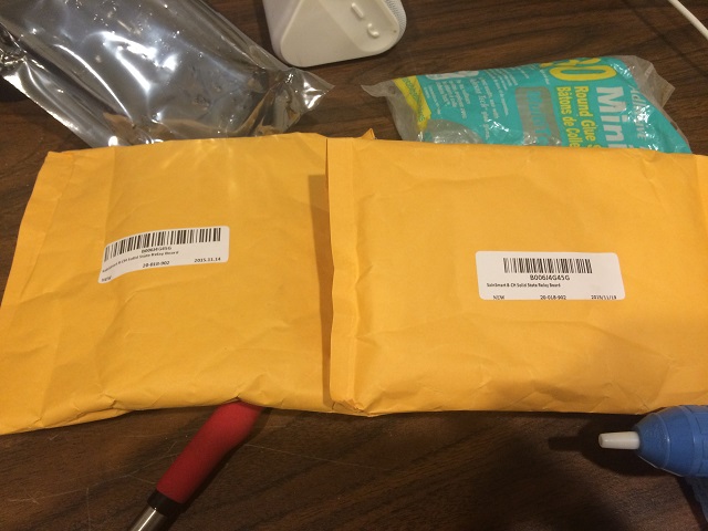
Those are my new daughterboards. I am very surprised. Mike ordered them at 3:44PM on Saturday… I got them delivered at my door at 10:00AM Sunday… I wasn’t expecting that. It put me in a really good mood all day.
I have been trying to teach my daughters that with any good project the most important part is “clean up”. Without cleanup you can’t start any new projects because everything is such a disaster. And with this particular project we will be working with some high voltage (not that high… but enough to really hurt someone) so making things clean and tidy is imporant. Here is the mess we have left after yesterdays fiasco.
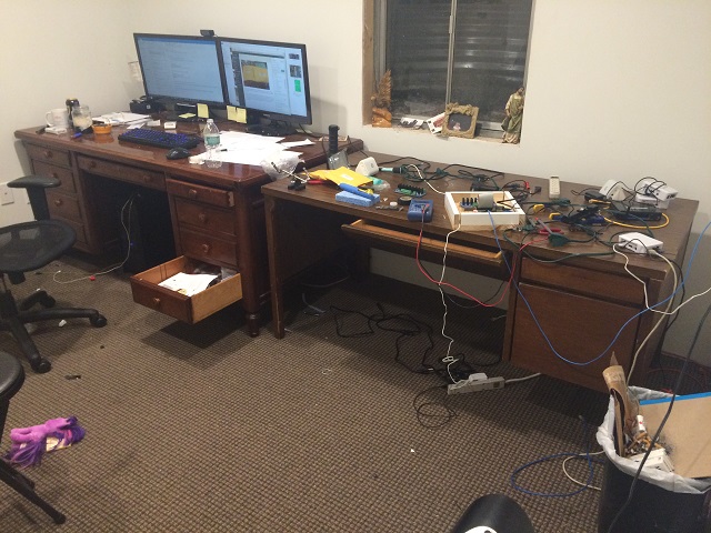
It is a disaster… I have to work tomorrow and have a lot of work to do for customers before I can start back on the project. This entire mess has to be cleaned and organized.
Oh.. By the way… The first daughterboard is dead. I asked Hannah if we should throw it away or save it for spare parts. She said, “Save it for spare parts”. Smart kid. If we blow out one of those driver transistors for some reason, I think all 8 of those are still good on the broken daughterboard. I wouldn’t trust anything else on that board except maybe the connectors. I just have to remember to mark that sucker as “BAD” with permanent marker as visually we can’t tell the diference between a good board and a bad one and now that we have three of them floating around the office it could be a problem especially with a bunch of kids milling around through the whole thing.
Crap… I have to clean this up all by myself because the kids are in bed. Uuugh!!! Oh… and we used a hot glue gun to place the old broken daughter board in our case. I have to figure out how to remove that.
2015-12-06-10:30PM
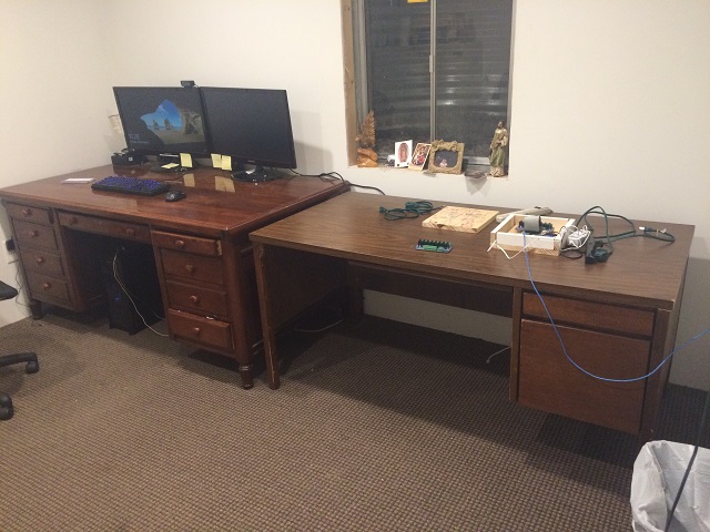
Now that is more like it… Ready for work tomorrow and now I know what to have the girls do next. Swap out the fried daughterboard for the new one.
2015-12-06-11:27PM:
I am thinking about what I can have the girls do tomorrow. I did notice that when working with the “hot glue gun” it isn’t really hot. I need them to remove the broken daughter board from the system. I thought about this a lot tonight and I do have one of these.

Now I don’t use that heat gun a lot, but I do remember that it can get so hot that the tip actually turns red. It seems dangerous. But we are talking about teaching my girls STEM! They may get a little burned but it is worth the risk. I am going to have them melt that “warm glue” gun glue right off that daughterboard and they are going to install a new one. Wired correctly (no high voltage though… I will do that part) so we can see those pretty red LEDs light up when we run the program from the motherboard.
SPECIAL NOTE ON HOW DANGEROUS THIS IS:
I wanted to break from my normal writing to actually mention to anyone who doesn’t know that this project is actually dangerous for children. My kids are using power tools, soldering irons, and eventually this device will be able to output voltage that would shock and possibly kill any one of us in the wrong situation. With that said… Go ahead and definitely try this at home, but make sure you understand what you are doing and watch your kids when they are around the device and tools, especially when you put VAC120 into it. GO STEM!!!
2015-12-07 – 9:24pM
So I had to work all day and didn’t get back until late. I had the girls use the heat gun and swap out the broken daughter board. They rewired it and now we have this.
Based by what I saw on with the multimeter testing this is what I was expecting. Two flashes for each light sequentially. Basic stuff. Pretty boring, huh?
Well what if we spice things up??? Let’s make this sucker talk.
Now I know what you are thinking… You are thinking, “Oh by all means make it talk, but don’t make me read through a ton of troubleshooting you have to do to get that working!”. To that I say… Request granted. The girls won’t be needed for this part as it is too complicated and guess what else? I already have all the code necessary from another project I worked on this summer. As a matter of fact I have a system image for a talking network monitor I built this summer that I will just download into the flash card on the unit and we will run with it.
2015-12-07 – 11:45PM
OK… Going with the system image of my talking network monitor didn’t work. Apparently my temperature sensor, which we don’t need for this project, was on GPIO7 which made that last light not light up and was sending me emails with the subject line “** PROBLEM Service Alert: Computer Room/temperature-sensor-monitor is CRITICAL **”
It is a whole thing. Instead I have to integrate the text to speech system into the original system image we already saw work. I will mess with that now.
SPECIAL NOTE: I have been an IT guy for over 25 years and it appears to me if anything needs sound I will have a problem with it. I think nice sound is my curse as it always gives me the most trouble. I know audiophiles and they have no problem with sound. I would like to be an audiophile too, but when it comes to making something “sound right” I just haven’t had good luck with it. As a secondary goal of this project I will be pushing the envelope on making this silly little beast sound good.
Now I boot back up with he image we were working with earlier and install a text to speech program called “espeak”.
Here is an example of very basic text to speech.
There are quite a few problems with that, the first thing I need to iron out is I want those lights to flash like the box is actually talking to me. Let’s figure that out first. I want at least a couple of those lights to blink when the device talks.
OK… Here is what you are seeing…
The lights here responding to the voice but there are several problems:
- I don’t want the voice to go through the 8 channels. The software I use to drive those has this HUGE delay.
- Also if you notice all 8 of those LEDs are lighting up depending on what is said. I don’t like that either. I want a dedicated channel for voice. Those 8 are going to be used for something else.
- I hate the voice. I don’t want a robot. I want it to sound more human.
- Oh… And it isn’t loud enough. I want the voice to be loud.
2015-12-08 – 9:00PM
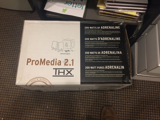
That is quite a list. Lets attack the volume first because it is easiest. I want to make sure I have a lot of control over the range of volume this produces. I also don’t mind it being obnoxious, so after mass tonight (Holy Day today… Feast of the Immaculate Conception. Yay!”) I went to the store and picked out the loudest most heavy sounding speaker system for a computer they had.
Next I am going to attack the voice quality because I have done that before. It will take me a while and I won’t bore you with the details, but it has to do with uploading the text to a specialized translation site from Microsoft. It is a very crazy thing where I can actually have the text translated into a few different languages before being output. For now I will just use English.
For this I didn’t attach the new speaker system to it because it is so late and I want the bigger girls to help unbox and connect it and they are asleep. I had the computer say this because my 1 year old (Kasia) was demanding that she hang out with me. This ended up freaking her out and she was happy to go upstairs to mommy.
That is pretty good. Better than the robot voice for sure. I didn’t put it through the program to light those LEDs because I don’t want to have the text to speech work that way.
So here is what is left for me to figure out before I wrap this project up and play a video of the final project:
- I want a separate channel… Or better no “channel”, just an output just for when this system talks using the text to speech synthesis.
- I need to wire up the 8 channels so they can control 8 – 120 volt devices that I will be connecting to it.
2015-12-09 – 10:32PM
I am out of time and don’t have the luxury of giving too much detail (I know… I know… Everyone is sad because they love the play-by-play… Just kidding… I know no one is sad). I have two very important customer projects to work on and it is way more important for me to be obsessed over someone else’s project than my own because well… I can’t do any of my projects unless I have money… Motherboards, daugherboards and speaker systems don’t grown on trees. So let’s wrap this puppy up and call it done.
So I had to drop the 9th channel idea for the voice and handle that the way with all of the channels like we saw earlier. I will have to live with the delay (I tried to resurrect a component off of our fried daughterboard, but there is nothing on there that is good anymore… I planned to write about it too, but it is a no go so we will have to throw that in the garbage… no spare parts from it).
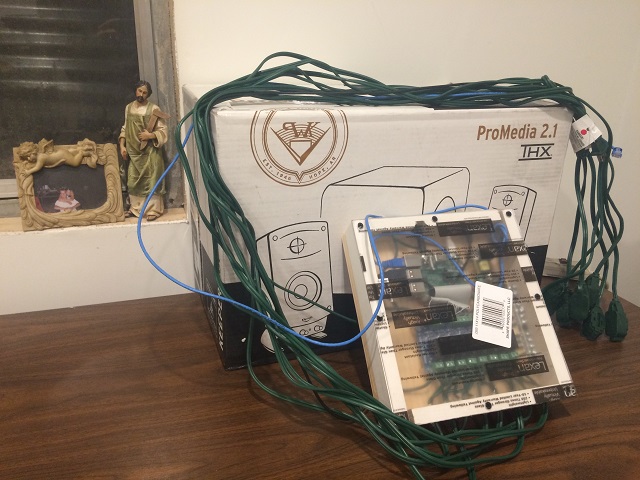
The other day I had to go to Menards and while I was there there were super cheap (like under 2 bucks) extension cords. I bought a bunch of them.
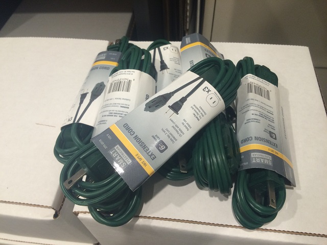
That picture is deceiving… I bought way more than that, but you get the idea.
I drilled holes in the side of our case (9 of them because I was hoping to figure out that voice channel back then) and marked them for each channel. I chopped the plugs that go into the wall off so I only have the outlets. I stripped, measured and tinned each end.
I grabbed a power supply for a Raspberry PI and busted it open and took out the power supply inside it. I used the hot glue gun to fasten it to the case.
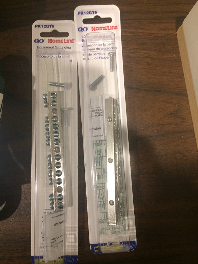
I bought a couple of these so I could connect all of the 120VAC inside the case.
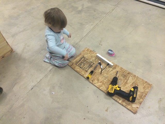
I also grabbed an extension cable I had for audio to bring audio out of the box (I had to carve out the back of the case a bit so the plug would fit. I also chiseled out a place to use a USB extension to bring a USB output on the case itself. I don’t want to have to open it to connect anything and it will have a USB wireless adapter connected to it at some point (Maybe not today… but at some point). Here is a picture of Kasia helping me chisel stuff to make the box (that was poorly measured) have everything fit.
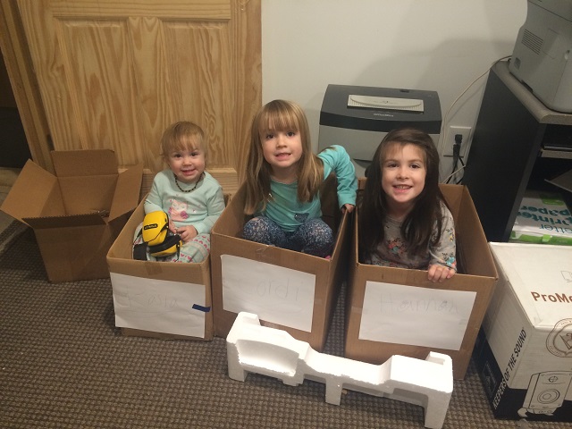
The girls were totally much more interested in playing with the leftover boxes from the Christmas presents I bought for customers than anything having to do with top secret CORHAKADA They did this when I wasn’t looking. I am not sure what is going on there, but they seemed happy.
Anyway… lots of drilling, a little carving, lots of soldering by me (I did a huge amount after the girls went to bed)… We have this.
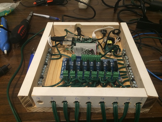
This is how it is connected: On the right are all of the neutral. On the left is the power that is fed to each of those eight channels. The idea is that as each GPIO is told to turn on… They will turn on.
Now there is HOT HOT HOT power going through this system when it is plugged in. I know it is a fire hazard because it is made of wood, but I don’t have time to mess with any of that. I just don’t want my kids to get shocked so I have to put a cover on it.
When I was at Menards I bought some plexiglass. I want to be able to see all of our hard work after this thing is done. I did keep the girls busy with decorating the top. Which would you choose for the top? Clear plexiglass or their decorated top?
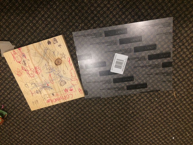
I chose clear plexiglass. I am sure the girls wont mind that I used that. I carefully cut the plexiglass and drilled holes in the top to fit on our case. The end result is this.
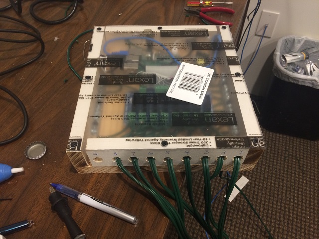
Now I peeled off the back that is going towards the case and left the top to be peeled off for the girls tomorrow. I want them to be able to peel that back themselves (even the baby can help because it is safe) and see what we all did together. It will be HUGE!
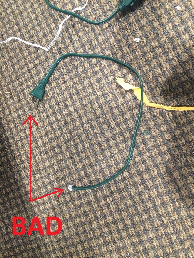
I did a quick cleanup. VERY IMPORTANT if you try anything like this. Don’t leave cut power cords lying around the house. These go in the garbage in the garage, not the garbage can in the house (I just know the baby will figure out how to plug that into the wall and I just know she would stick the other end into her mouth… CLEANUP! most important part of a any project, but especially a project like this).
So here is where we are… I was in a rush… After frying the first daughterboard I did my best to really figure out how to get everything connected. I didn’t test this… I just assumed I knew what I was doing. I didn’t even plug it in after putting all the wires in. Tomorrow I will have the girls unbox the speaker system, pull off the protective layer on the cover and plug it all in. The next post will be the final post (I hope) if I don’t run into any problem that is worth writing about.
Finally… Did anyone figure out what this device does yet? I told my wife tonight and she was pleasantly surprised. That is a really good thing. She never is interested in any of my projects, but this one she likes. She doesn’t even read any of my blog posts. For example… I could say:
My wife is the neatest person I ever met and I am so happy I married her. I look forward to every day because she is so great. I brag about her all of the time with friends and family because she is so good at being a mom. I tell everyone that I “love being married” because I remember being single (I loved being single…. but being married is so much better).
And she would never know.
To continue on to the next and final post on PROJECT CORHAKADA click here.

Recent Comments