
This is my third post about my attempts to make a video camera that I can stick in my pond and see from my desk. The first post it was about connecting the antenna to the wireless camera and that went really well. The second post was all about power. And it didn’t go so well. We were left with a lot of unknowns and maybe even a broken camera.
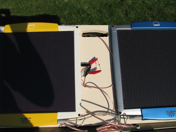
If you recall we left the solar panels and the batteries outside over the last two days. It rained some and got everything wet. I know those panels are water resitant, but they are kind of old and maybe they are not anymore. I think I will start there. – I know some of you are thinking, “TEST the camera first dumb dumb!”. I don’t want to test the camera now and am just too afraid it is broken. I was careful with it, but there was a lot of things that could have happened with it out there. That camping table I had everything setup on was aluminum. Maybe some of the exposed components got shorted. Or maybe it just got to hot out there in the sun and got fried. I will test that later. For now, here is a picture of our solar panels and battery.
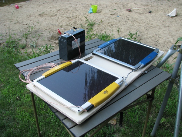
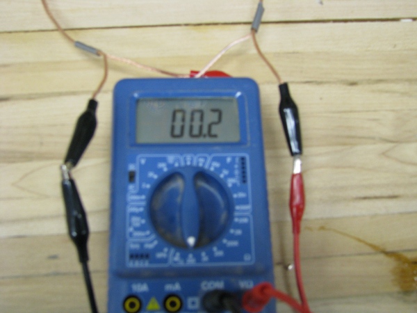
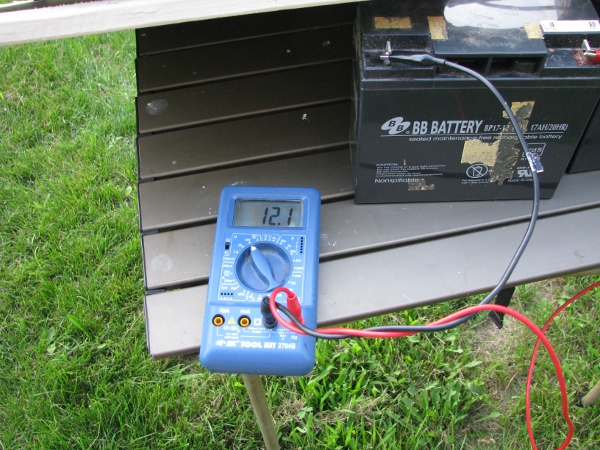
I really need to see if they charged at all over the last few days. I will stick a meter on them.
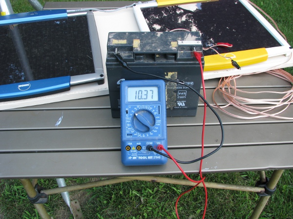
Nope they didn’t work. That should read 12 volts. At 10.37 volts, it is clear they didn’t charge. I am not sure what is wrong. I will think about that more later, for now I have got other things to worry about.
Whenever I start my day and I have a lot of difficult things on my to do list that I am not sure how to solve, I do the same thing. I start by cleaning my office and organizing my workspace and desktop. This allows me to know where everything is and have lots of space to move around and place things that are pertinent to the high priority project(s) at hand. This works very well for me in my work life, so I am going to apply it here.
Yes… I know… I know what you are thinking (Test the camera!). I can’t test it now, it is too scary. It might be dead.
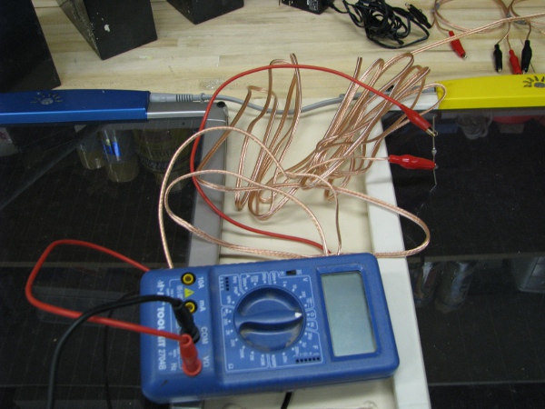
I know when I brought everything in the other night, I just piled it all on the workbench that I was working at the whole day. There is all sorts of stuff on there that has nothing to do with the problems we are dealing with right now.
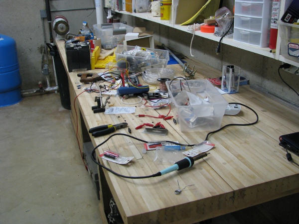
So I will clean this mess up. Put everything away that we know we don’t need right now. Then only bring in things that we need to fix things. We may need those 12 batteries that are stuck together with sticky tape, so I will separate those and clean them up a bit too.
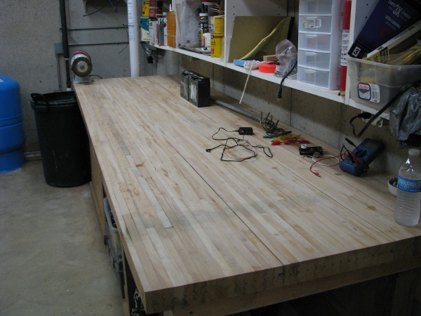
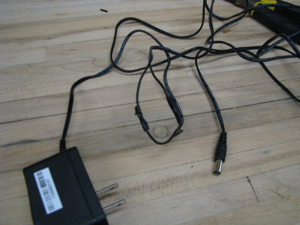
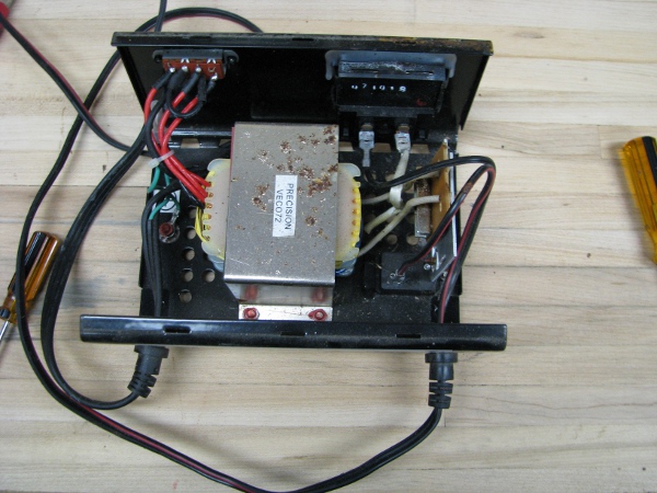
That is better. Now we can focus on what are problems are. This should help a lot. With only the stuff we are concerned about on the bench it seems obvious to me where we start. It isn’t clear on the picture above, but I did butcher the power supply for the camera. If we are going to test the camera it, I need to fix that power supply.
Now I don’t want to take apart our 5 volt regulator assembly. That worked well, at least I think it did. So I will need another end that will fit into the camera. I have a pretty good idea where I have one of those. In here….
After some moving things around a bit I find this.
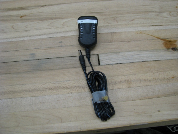
The extra bonus is that I can use the whole wire and not have to worry about the supply (Because when something is broken, I tend to put a label on it that it is dead, so I know we can get rid of it). So I clip the end off near the transformer. Then I tin and solder together the wires. This is absolutely overkill. I would normally just twist them together and tape them for insulation. I don’t want to do things super quick until I can get some confidence back. Something went wrong in the first attempt at powering up the camera. I was being rushed. I got too exited and may have broken the camera. So for the next few steps I will be extra careful not to mess anything up. Here is a picture of me tinning and soldering the wires together.
Add some tape and now we have a fixed power supply.
Now I can’t just plug that into the camera. I may have done something wrong and reversed the wires, so I need to test it first.
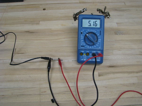
OK… Now we are safe, let’s plug it into the camera and see if it will actually turn on.
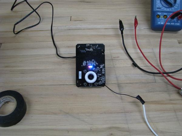
Yep… We see lights, that is good. Let’s move on…
I know… I know… It is ON, just test it already!!! No I am not going to test it now. I am too scared. It might be broken. Aside I will have to walk up two flights of stairs, go to my computer and then grab screen shots for the post if it works or not. I am in no mood to deal with a broken camera right now.
I lost my train of thought… Oh, that is right, I want to reiterate being careful with electronic devices when you attempt projects like this. You may have noticed in some of my pictures, voltages and other things may have been reading negative. The reason they read negative is because I reversed the polarity. Way before my time people figured it all out and had color coding, red for positive and black for negative. It is supposed to make it easier. If I have accidentally messed up on the polarity on measuring with the meter, I could just have easily messed up on that polarity plugging in the camera. It wouldn’t be surprising as I go through past pictures that I messed something like that up. So I have to fix something. Here is a close up of the problem.

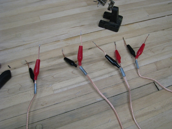
All of the connections I am making are for power right now. When dealing with power it is best to deal with red and black jumps. We will try to avoid the accidental negative readings from me being sloppy. If you notice we are missing a black one from this set and we wont use the green or yellow one unless we have a separate connection to make that is unrelated to positive or negative power flow. I know you can see right away, there is a red one and are thinking, “Where is the black one to that set?”. My answer, “I have no idea. I saw it for a few seconds when I first pulled them out of the bag, my kids were around and my guess is that they took it. I asked them and they have no idea. Soooo….. I have to solve this problem next.
If you remember from the last post I did on “power” I found a bunch of alligator clips. I used one of them to replace my multimeter probe. I am going to use the rest to make some jumpers. Here is what we have.
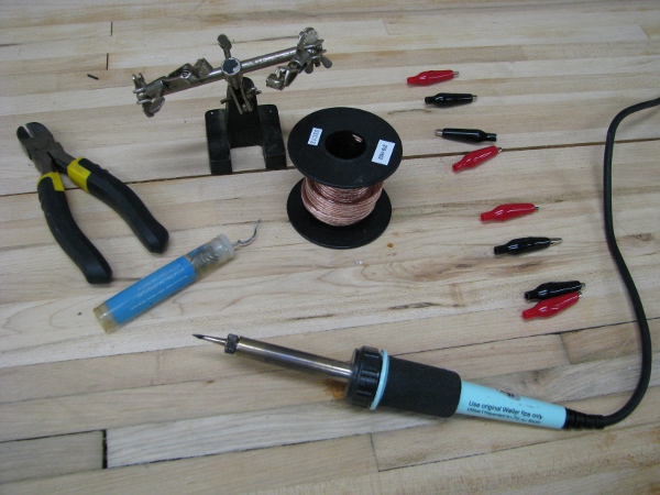
I cut the wire to nice lengths and separate the ends about four inches down. I wrap duct tape around the separated ends so my kids don’t pull them apart when they see them. I am careful to place the cushion rubber jackets on the wires first because I don’t want to solder a clip in place without the jacket behind it.
I am very careful to make sure the positive matches the positive for all of them.
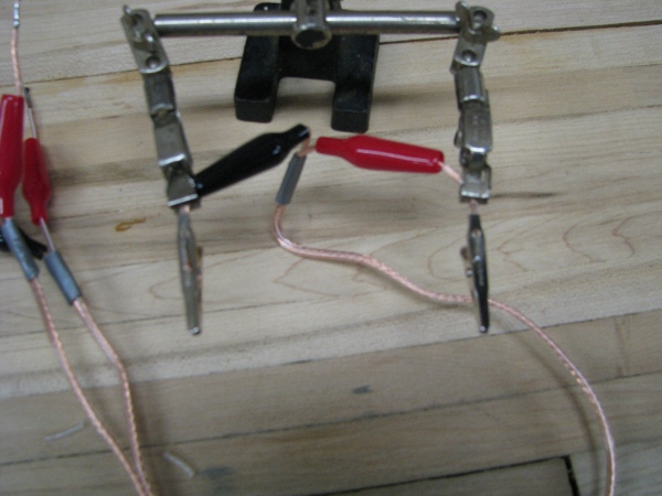
Notice the clips of the helping hands are not on the metal, but on the insulation. I don’t want them touching that metal because it would dissipate the heat too quickly. I want to get the clip itself as hot as possible with the iron to get a good join between the alligator clip and the copper wire. When I am finished I have these.
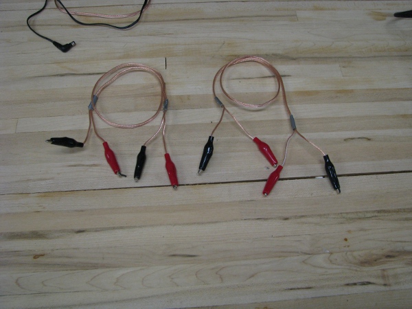
Of course I can’t leave it there. My confidence is shot on making sure things are right now because I may have blown the camera, so I have absolutely no confidence in these cables until I test them. I test them all with the meter and they are all perfect.
Now that I have a couple of jumpers that will work really well and my kids won’t tear apart, I can focus on something else. One of the things that made it difficult in testing things out at the pond is that I have to run up the front steps, then upstairs to my office on the other side of the house every time I want to test things. I do have a netbook that would allow me to do any test from outside. I made sure it was all charged up over the last couple of days so I can use it outside without plugging it in.
Let’s bring it outside, boot it up and connect it to the wireless and see if we have connectivity.
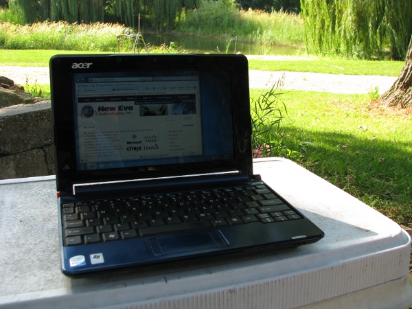
This part was really easy. This is going to save me so much time it won’t be funny. I am going to close it back up and bring it in the house for now. If I leave it outside one of my kids may throw it into my ornamental pond (We lost a digital camera that the kids use and one of a pair of shoes that light up when the kids walk this year because kids love to throw stuff in water and have no idea what they are doing). – Note: The ornamental pond is different than the pond that I am going to put the camera in. The ornamental pond is filled with fathead minnows and is right next to the patio that overlooks the pond and is right next to the house. I may make use of the ornamental pond in this project. It has a power outlet right next to it because it has a waterfall. And is also super close to the house so wireless totally wouldn’t be an issue (The netbook is literally two feet from it in the picture above).
In the beginning of this post we tested the battery that was supposed to be charging over the last couple of days by the solar panel. When I measured the voltage it was 10.37 volts. That is 12 volt battery, if it had any real charge in it, it would read 12 volts. I need a way to charge those batteries.
I do have one of these. But I think it is broken.
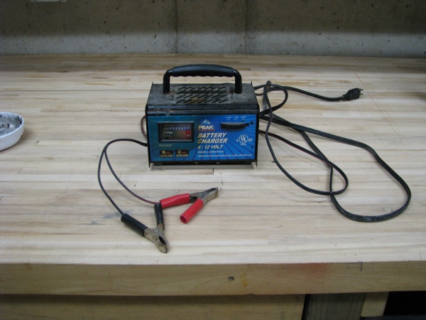
One of my sisters was over a couple of years ago and her car battery died. My wife and her decided to hook it up to the charger. Apparently they didn’t know or weren’t paying attention at the time, but connected the black to the positive and the red to the negative. I hope they read this post so they know that you are not supposed to do that. It has been a while since I tested it, so I can’t be completely sure if it is dead, so let’s plug it in and test it. Notice the top of the unit where it is rusting and the face of it where it is a little discolored. Those are both signs of a lot of heat. The paint on the top got compromised and the face of the unit looks like it has had a lot of heat. This thing really might be dead.
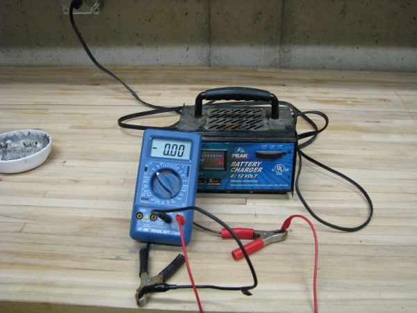
Yeah… This sucker is dead. I am a Pollyanna by nature, so I have to open it up and hope that a fuse got blown and it will be an easy fix.
More signs of corrosion. I test everywhere, before the fuse the inputs an the outputs and the only thing that tests OK is the cable going to the unit itself. This sucker is dead dead dead. I pull the clips off of it and the ampmeter because they might be OK still. The rest is junk.
It has been a few hours since I took that first measurement of the battery that was charging out in the sun and rain for a few days, so I had a chance to think about it. I don’t know a lot about solar cells. What I learned about them over 20 years ago in college is really spotty. I do remember a lot though, I remember “solar fatigue” where they tend to lose output over time in the sun. But that is not our problem here. If I had to guess, when it is dark the solar cells actually put a load on the battery. So overnight they are draining whatever they put into it. That battery had a few days to charge and even in a little bit of sunlight they should have still been charging.
If you recall from my last post, I told a story about when I was a kid and how I put something called a “diode” in series of the output of a transformer to get a DC motor to turn a little. We need one of those. Why? Because we need to protect the batteries if the solar cell goes dark and starts to draw current instead of output it. I would like to mention here, that I don’t know a whole lot about how these solar cells are constructed. I would think if that were a problem they would have diodes already in them, because that would be a cheap problem to solve if they were going to be used to charge batteries (which is a super common application for solar cells). Anyway, I don’t want to call the manufacturer and would rather try the diode solution.
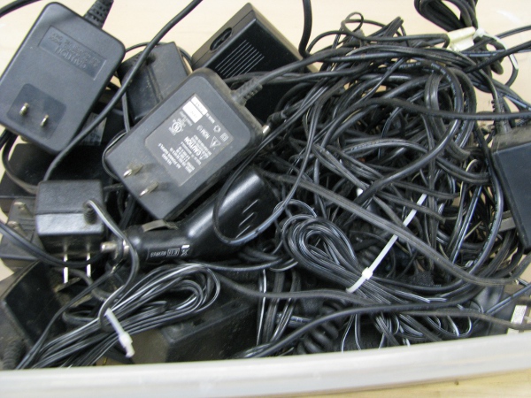
I know what you are thinking, does he have a diode that will work for that? I think so, but not sure… I do have a box that looks like this.
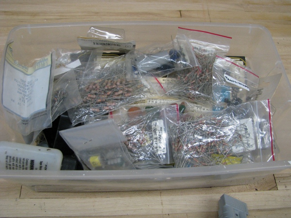
I literally haven’t looked through any of this in like 15 years or more. These are left over from when I was in college. The only reason they are in bags is because at my old job I brought them all in to work because I erroneously thought I would need them and one of the techs that worked for me (who was a total clean freak) put everything in bags and labeled everything. It should be easy to find what I need from it.
As I am rummaging through this, I find this:
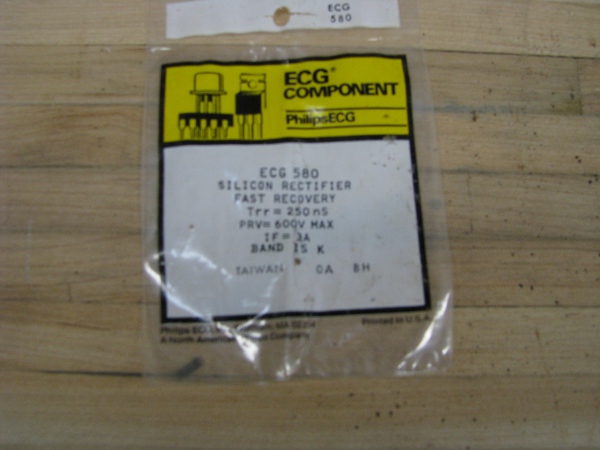
Now I don’t know why I would have bought this. It doesn’t look like a diode and it does say rectifier on it. If it were a full wave rectifier it won’t work. I like it that it has “3A” on it. I don’t know what “IF” means, but 3 amps is way more than the solar panels can do so I have to try it. Perhaps it isn’t a full wave rectifier and the label just means, “rectifier diode”. I don’t have an oscilloscope or a function generator so I can’t prove anything about this little thing. I will have to try it. I should note the only reason I am trying this is because it looks beefier than the other diodes in the box. Here is what it looks like when I take it out of the bag.
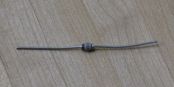
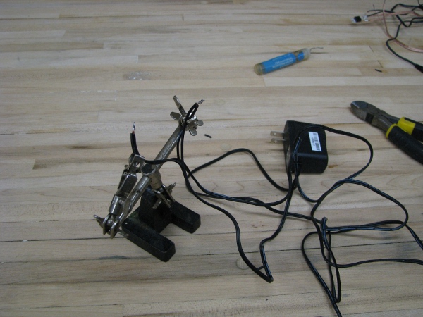
Those terminals on it look pretty heavy duty compared to the other diodes I have. I test it and in the workshop it really does appear to act like a diode. If I connect the ohmmeter in one direction I can see a closed connection. If I flip the wires around I can see that it is completeing the circuit. If this was a full wave rectifier it wouldn’t have done that at all. It is probably just a diode. So I go to bring the whole assembly outside. But it looks like this.
Now normally I would just deal with this mess and bring it all outside. But not today. Today I am careful. IT guys will enjoy this simple solution. I need to do some cable management (IT guys are always dealing with lots and lots of cables). I go to my car and pull out this:
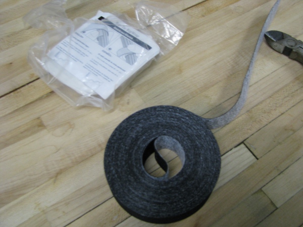
And now my mess looks like this:
Now that that is cleaned up. We can go outside.
Yes… I know I know… The camera is probably dead. I am just doing every little thing today to avoid testing it. It has been bugging me now too. It has been bugging me for the last two days, I have to test that later. If the camera is dead I may give up. I am having too much fun. The camera can’t be dead.
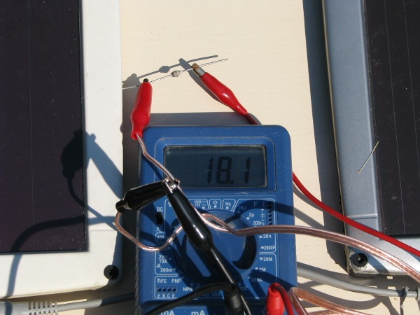
So outside, I connect everything up and I test. Notice the little mark on the component facing the right. Now also notice the voltage.
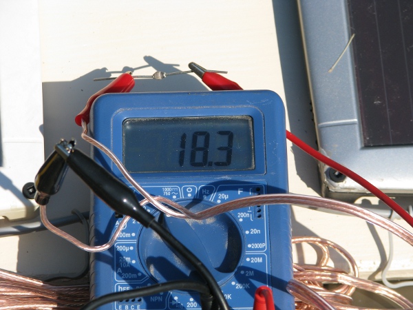
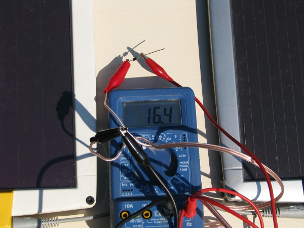
In this picture I reverse the rectifier. Notice the stripe on the component facing the left, also notice the voltage.
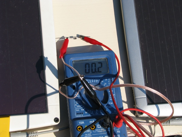
That isn’t right at all. This device is a full phase rectifier. I have no idea why I bought it or what I used it for. I am the type of person that if I see something in a store I may just buy it because I think I may need it someday. So perhaps that is what I did. No rectifiers are needed in the circuit. At this point, we only need a diode. So I got back to my box and pull out something that I know is a diode. I don’t look at anything but its terminals and if it has a clear glass coating. If it looks like a wimpy thing that can’t take the current, I don’t use it. Here is what I end up with.
Here is the picture, if I reverse the diode…
Now that is better!!!! Too bad I got all distracted with that rectifier. It is good to know that I have one of those though. I wish I had one of those when I was a little kid. It would have sped things up.
I still need to connect the battery and make sure it is actually charging. In this picture, I am measuring the output voltage of the diode/solar panel assemble connected to the battery. I do this measurement because I want to make sure that will be charging!
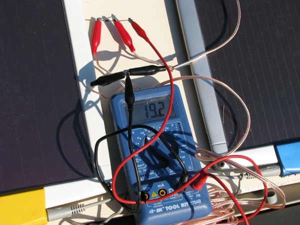
Everything looks good. Let’s take the meter out and just leave it there for a while. Note: The battery is behind the solar assembly holding it up toward the sun. I think this makes a lot of sense because there are trees on the other side an this may get the panels more exposure.
Now with us getting power to the batteries and charging them (hopefully). We can move along to testing the camera. I know I know I know… It is ABOUT TIME!
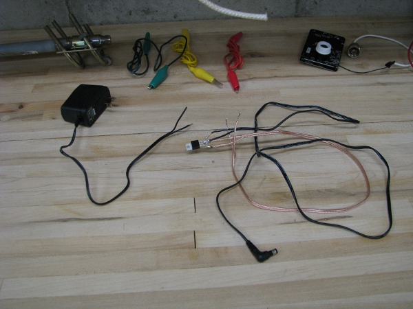
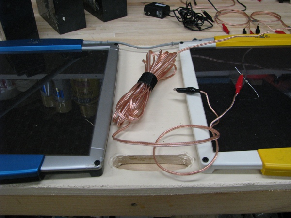
Here is what we have for testing the camera. It should be super easy to test.
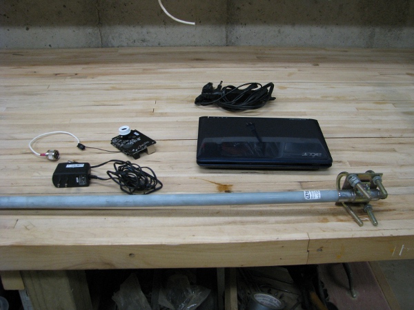
We have our antenna, our camera, our fixed power supply (That we tested to make sure it works after soldering those wires), a power supply to the netbook. Oh… I notice something I don’t like in the picture.
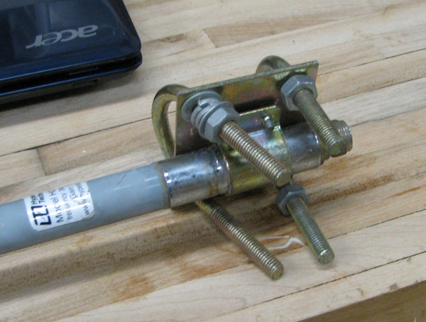
That bracket is a mess. I should really clean that up. I am going to pull off those mounting brackets. There are too many washers on that and they didn’t mount really well to the roof mount assembly by the pond. Let’s fix that first.
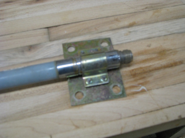
That is better. Oh… The UPS driver just stopped by and dropped off a package. I know what that is.
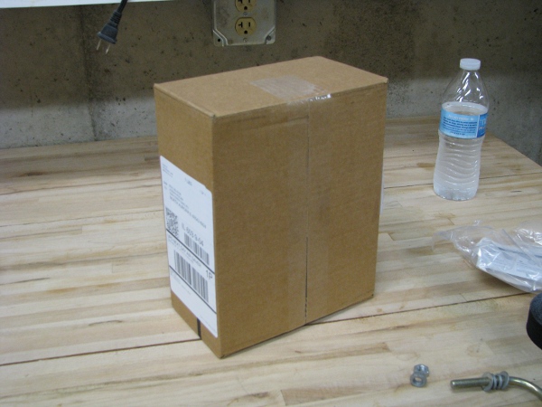
It is my replacement phone. The stupid USB port to my phone is broken. This happens to me every couple of years because my kids don’t disconnect it “nicely” from the charger when it rings. We are always telling them to do things “nicely” but they are kids. What can you do? My phone is actually dead when this package arrives. I have been charging the batteries in a way that could literally eat up a few posts on this site. For now I really need to stop and take care of my phone so my customers can reach me if there are problems.
After a lot of messing around getting my new phone working and taking my kids to my neighbors to swim I have some time now. I will get back to this project. Where were we?
Yes. That is right, we have solar panels charging up batteries on my camping table out by the pond. It is still light. Let’s check it to see if it is charging.
Now that looks pretty good. The battery does have a charge. We will have to check it again tomorrow, but for now this looks pretty promising.
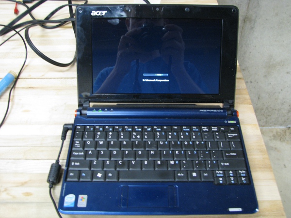
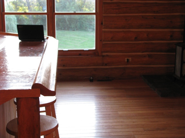
At this point I can’t think of anything else that I may have to do to keep me from finally testing that antenna. So I bring only the camera, its power supply and my little netbook into the kitchen where I last knew it worked. It looks like this.
If you look closely you will notice two things. Their is no antenna. That is correct, because it shouldn’t need one. I moved the access point in the last post and it is literally 6 feet beneath the camera. As a matter of fact, the end that would connect to the big antenna is pointing in the direction of the access point through the floor. The other thing to notice is that there is no lights. When I first plug the camera in it showed lights and then they turn off. I don’t know why it is doing this. It reminds me of what I was seeing when I was messing with it outside. The lights turn on and then turn off. I think it may be dead.
I am not sure what to do at this point. I want to continue the project, but wonder if I should just scrap it. It has been a lot of work and I didn’t really get anywhere with it. I decide to order another camera if it needs be. I will order the exact same thing because I have invested too much time with this particular device.
In the back of my mind though, something else was going on. I do kind of remember trying to get the power going to the camera and turning off sound and the lights in its software when I was connected to it. That seems so long ago, but I should at least check it to make sure it isn’t really dead. After all it would make sense, it shows lights to tell you it is on until it gets instructions from it memory to turn them off.
Let’s see what is going on from the netbook.
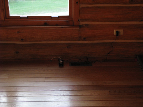
Here is where I placed the netbook to cut down on my running upstairs/downstairs and everywhere in between.
I should be able to see what the camera sees from the netbook in the same direction if the camera is still working.
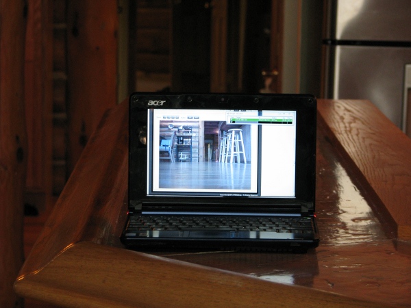 ]
]
It works!!! It works!!! The camera works!!! I have been dreading this moment all day and I didn’t break it! The camera shot is in the same direction down the hall that the netbook is facing. Even though we are in the same position that I thought we were after the first post on this project, I am very happy. I didn’t break anything. As far as I am concerned we are in much better shape than we were over the last few days. I have to stop now…. It is late… late… late.
To continue reading see Part 4.

So we still are not certain if the solar panels were draining the batteries at night, but we do know they are capable of charging that battery. Joe this camera is your Frankenstein’s monster – “It’s alive!”
Pingback: My silly PondCam – Part 2 – POWER!!!! | Joe's Lab