
OK… I did a lot today and was all over the place with this project. I discovered some interesting things along the way and I hope you enjoy.I have been doing so much today, I don’t even remember where we left off last time, so I have to check the last post. If you don’t remember either, you can check it here. OK… I remember now, the camera works and we still don’t know what to do about power.
I do know we have to get a better understanding of our power situation. I think it is best to test the batteries we have. There are three of them and I really am not sure if any of them are good or not. Since my car battery charger is dead, I really need to figure out how to test them in a way that would be meaningful. Hooking them up to the camera was a dud, we already tried that and it caused us all sorts of headaches at the end of my second post on this project.
What I need to do is put a load on the battery and measure the voltage across the terminals. This will tell me if it has any power. Remember Watt’s law? Power = Volts * Current. If I can put a load on the battery that closely matches the camera, I can see if they will actually work to run it. One thing is for sure, I have a lot of resistors in my little component bin, I will pull those out.
While I am looking in my component bin, I find this.
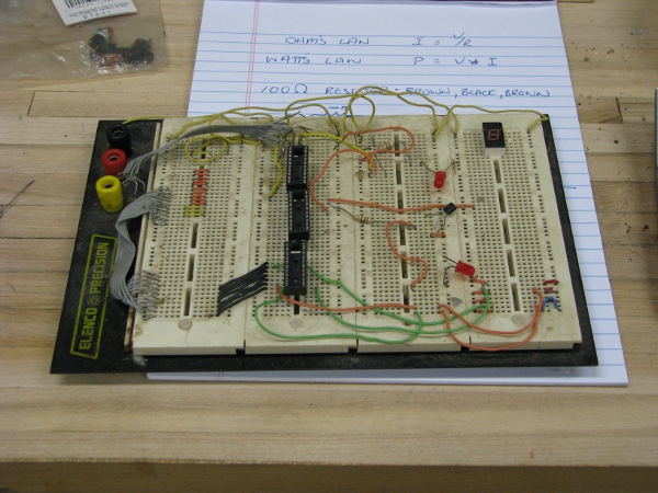
It has all sorts of parts on it left over from my final project when I was in college 22 years ago. I really like this board. It will allow me to build and test things without soldering them. It is 0ld and gross right now, but I stop everything to clean it up. I have a feeling I may need it for an idea that someone brought up on the first post.
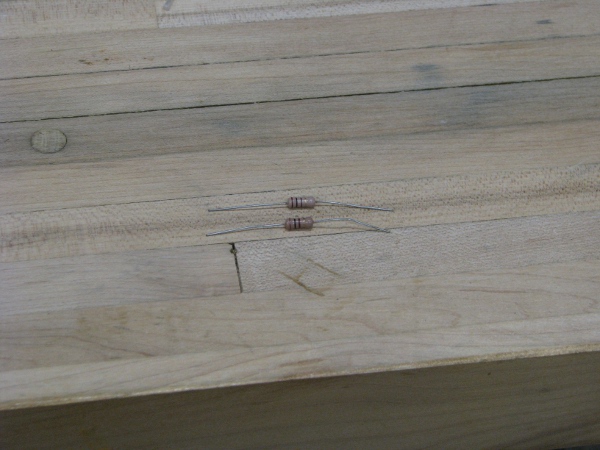
Back to my resistors. Here is a picture of them.
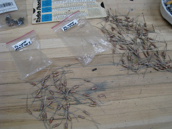
When I look at all of these I am reminded of my wife (she HATES bugs) and my little two year old (she HATES bugs too). Before I go any farther I want to turn some of these into something that looks like a bug.
I clamp a few of them together and coat them with some clear glue.
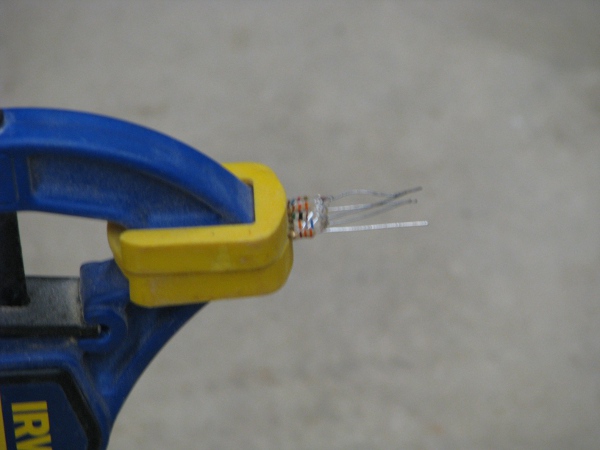
When this is dry I am going to bend those terminals down (and maybe a couple of them forward to look like pinchers) and stick it right under my wife’s monitor. I know you are thinking this is a bad idea, but I can’t resist. If it doesn’t scare my wife I will ask my kids if they think it is scary and let you know.
Back to the math: We know we have 12 volts (or somewhere near it) coming out of the batteries. We know our camera needs close to 300 milliamps of current. Here is what the math looks like if we want to see 300 milliamps across our batteries.
Volts = 12
Amps = .3
Resistance should = 40 Ohms
We need 40 ohms of resistance to test those batteries in a way that mimics the draw of the camera. If you notice on the close up of my resistor bug above, you will see little colored bars on each of those resistors. I know what those mean, but I can’t remember how to read them. We must look up the formula for how we determine how much resistance each of them has.
Here is a pretty good pic of what those colors mean.
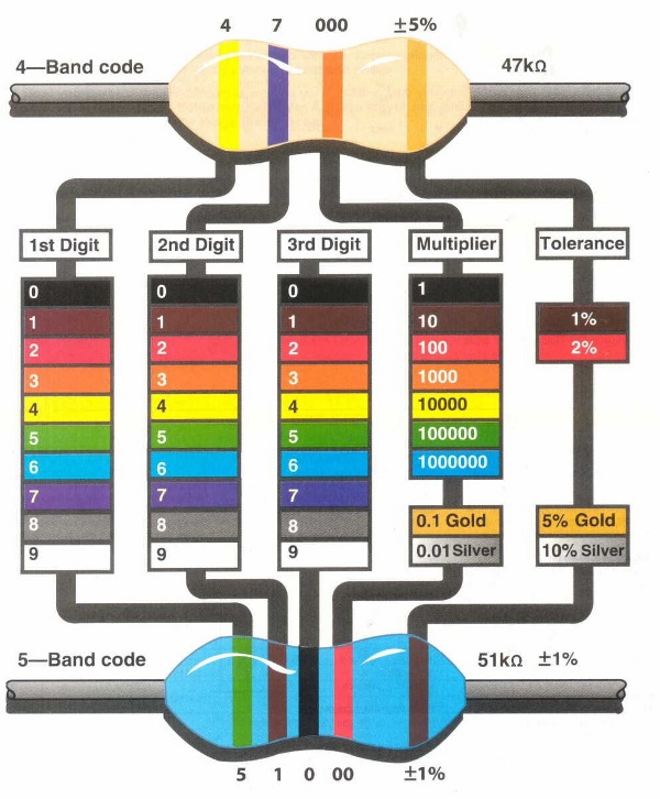
Now I know I don’t have a 40 ohm resistor in that pack, but it would be a pretty good guess that I have a few 100 Ohm resistors. I want to start there, so I want the first digit to be “1” which is brown. The second digit should be a “0”, that is black. The third digit should be “10” or brown. The last digit I don’t care about because that has to do with tolerances and I am not building a rocket ship.
So the first three colors we are looking for are BROWN, BLACK, BROWN. Let’s start looking.
After a little moving them around I find two of them.
A little more and I find another. I needed three and here is why.
If you put resistors in series (that means hooking them up end-to-end) you add the ohms together to get the total. So If I put three 100 ohm resistors in a series I would have 300 ohms. But if I put the resistors in parallel current has multiple paths through each so your resistance goes down. Here is the formula:
1/RT = 1/R1+1/R2+1/R3
.01+.01+.01 = .03
1/.03 = 33.3333
Our total resistance for three 100 ohm resistors with the ends of each connected together is 33.33.
If we put that on a 12 volt battery, it should be drawing 360 milliamps of current.
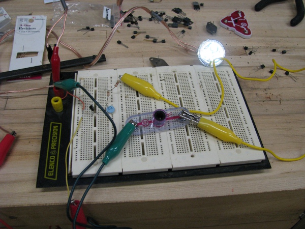
This is only a test so no need for solder, I am going to twist the ends together and we should have 33.33 ohms (or close to it).
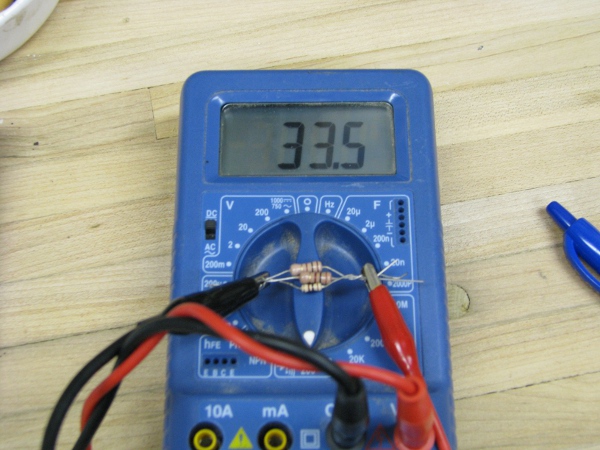
OK. That is pretty good. Looks like I did the math right. It is very satisfying to do a formula on paper and have it work out in real life. This is a good set of components to test our batteries.
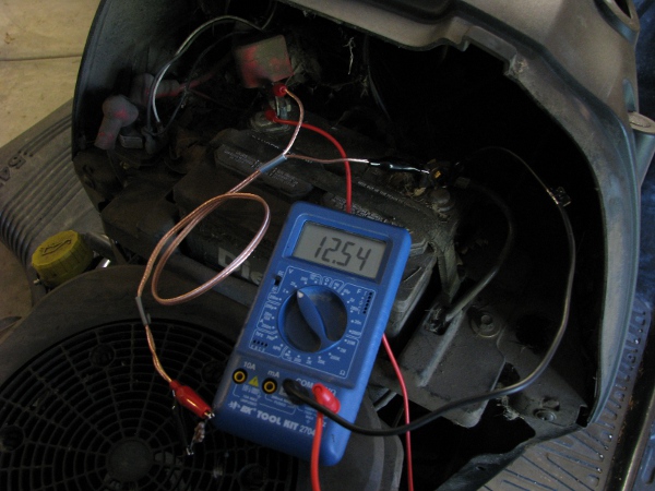
Lets get that battery we left outside in the sun charging for the last few days. I hook it up the voltmeter.
Well that looks promising. Let’s put our 33.5 ohm resistance across it and see what we get.
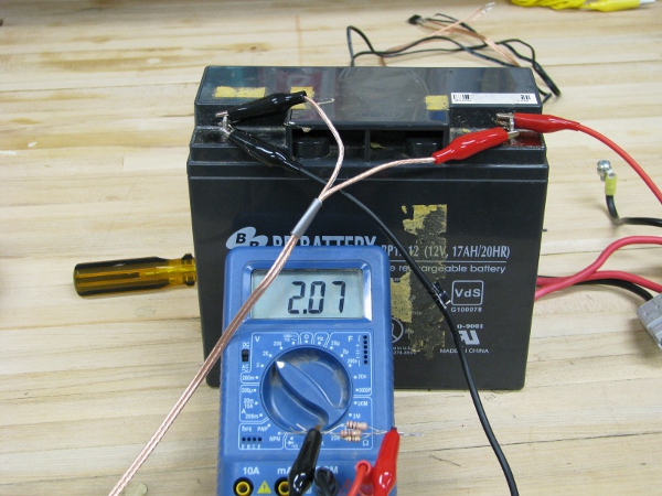
OK… 2.07 volts, that is really bad. I am not sure now if these batteries are dead (there are 3 of them in total) or if they are just not charging from the solar panels. Again, I have no charger, so I am not sure what to do.
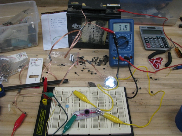
I grab another battery and it reads 6.09 volts under load. All of these batteries have been sitting in my basement for more than a year. I have no idea what kind of shape they are in, but it does look like they are all dead. I need to find a battery that is good so at least I can make sure I am testing them correctly.
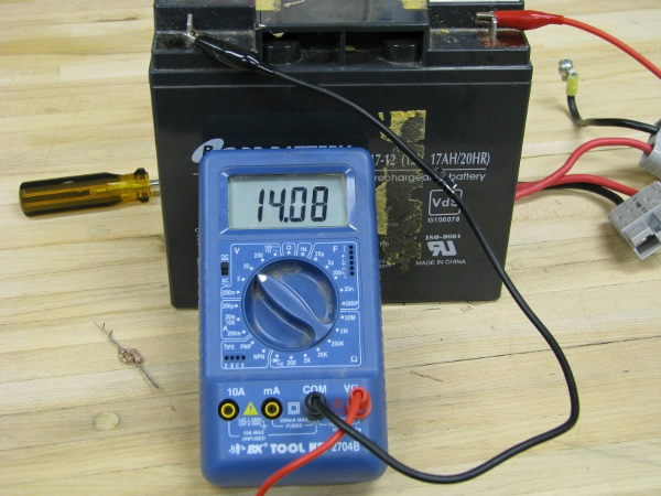
What I would expect from a battery like these is to put 33.5 ohm of resistance on them and have them still read 12 volts. I have an idea. My lawn tractor has a 12 volt battery and I know that is good so I will do exactly the same test there.
Just what I thought. Some or all of those other batteries are dead. I will have to figure out a better way to charge/test them to find out for sure.
Note: When I test with this little resistor assembly I put my fingers on them and notice they are hot. Just like our rectifier from post 2 that is wasted power in heat. I am reminded and bothered by our rectifier because of these two things about it; wasted power, lots of heat.
I have to move on from power right now because of the batteries. I already know things will work if we plug them into outlets from the house, so I don’t want to do anymore testing that way. Now that we know my power efforts were all screwed up and also know the camera works from our testing last post, I have some confidence back and want to move forward to waterproofing the camera.
I really want to get the case for this camera done for two reasons: 1) if it isn’t waterproofed it can’t go into the pond (obviously) and 2) messing with that camera without a case is a problem and when I move it around it puts weight on that little connector that connects the antenna. If I break that it will never be the same. Soldering microelectronics like that is really difficult and I don’t want to have to solder on a new MC connector on that little board.
My first thought about how to waterproof the camera was to use Plexiglass. It is simple to work with, easy to cut and glue and really easy to find. I go to Ace Hardware store. When I get there I ask the guy if they have any. He shows me some and it is all too thin. I ask him if he has any thicker stuff and he says it is “super expensive”. Now I am thinking, “This is ridiculous, how much could a small piece to build a box cost”. I tell him I don’t need that much and we go to the back of the store and he shows me a piece that is perfect for what I need.
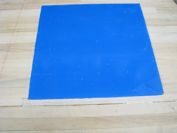
Since it is a cut off and not a full piece he doesn’t know what to charge me. I don’t say anything and try to be really quiet. He says, “I want to make you a deal on this piece”. He asks his co-worker, “What do you think we should charge for this?”. I feel like I am in a car dealership and he just went in the back to talk to his manager if he could thrown in some car mats. Then he says, “What do you think about 5 bucks?”. I do what I always do and say, “yes”. I probably should have said, “I will give you 4.75 for it” but I didn’t, because if someone did that to me I would be irritated (No one has and no one ever will call me, “Joe the great negotiator”, more like, “Joe the pushover”. Anyway… It doesn’t matter I have the exact material I need for waterproofing the camera.
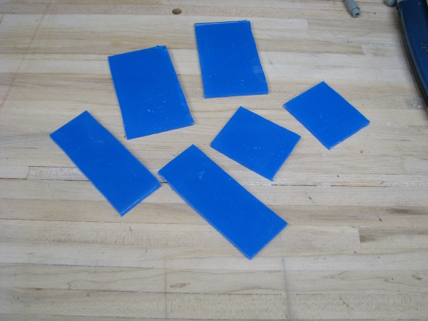
I have to figure out how to cut the stuff and ask the guy, he says to use a special saw. I ask my brother-in-law Oliver who is really handy and knows a lot of stuff and he says to etch a line and just break it clean. As usual, I don’t like any of that advice and I decide to do it my way and use a jigsaw with the blade I have in it. After bringing it home, I take a few measurements and cut it up quick and have this.
Now how do I put these together you may ask? Well… While I was at the hardware store I saw this!
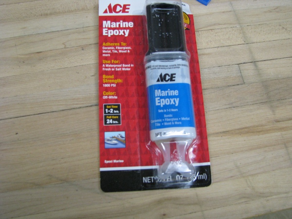
Epoxy is great, much better than glue. It doesn’t require light or air to dry, it bonds when you mix it. That is why there are two separate tubes. You have to mix this stuff to use it. The fact that it says “marine” on it makes me feel like it is the right stuff for this. I look at the label and it says “bonding fiberglass”, so I buy it.
And for good measure I bought this.
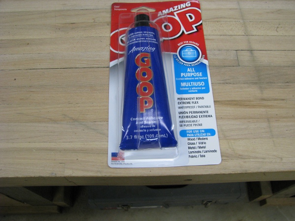
It is always good to have a bunch of goop glue around. It is really good for putting back the lowers of your kids shoes and fixing their plastic toys when they break them. I am going to use it for waterproofing. None of this tube will go to waste.
I peel back the blue backing on the sides that need to be glued and double check my measurements with the camera.
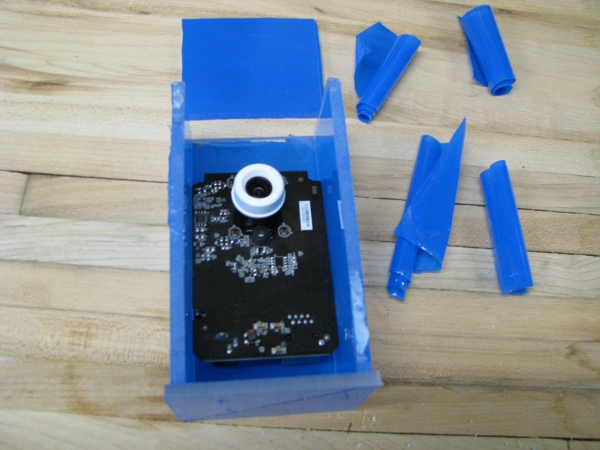
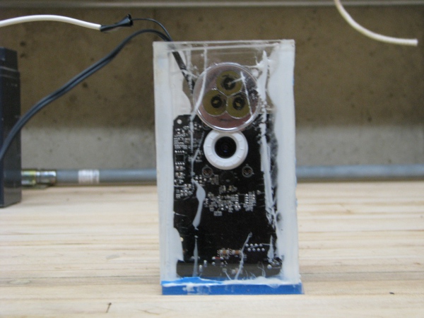
I mix the epoxy and put the box together.
Note: When I put this together I tried to clamp it, but it fell apart in the middle of it. Then it collapse while it was drying. Epoxy got speared around the edges and it wasn’t pretty. I was able to salvage the “hopefully waterproof” box with enough of its surface without smears, buy the end result isn’t as pretty as I thought it would be. I would have taken pictures of that catastrophe, but I was too worried that that epoxy would smear a part that we will need the camera to see through, so I quickly got it all put back together and couldn’t take a picture of it when it fell apart in the middle of me building it.
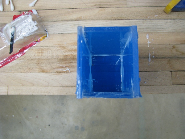
Once this is dry I have to test it. I was thinking of submerging it in water and see if water leaked in, but it would be way easier to fill it up with water at the sink, so I decide to do that.
Crap! This thing is leaking from two obvious places. This is probably my fault. I had a lot of trouble cutting those edges correctly and when I glued it together, I could see it wasn’t really meeting well on all edges. I dry it off apply some more epoxy.
While it is drying I have to use my time to make some progress in other areas. One thing I can’t keep my mind off of was Tim’s comment in the first post.
Tim is right. Just because we have clear water in the pond now it may not be clear all of the time. I did talk to Tim on the phone about it and told him I have an aerator and that the pond was clear. But as I think about it, I work late and wouldn’t it be neat to use the “light” feature of the camera software to actually turn on some sort of light so the camera could see better? I know I showed some screen shots of the software and can turn off the front camera light through it. Woudn’t it be neat to use that feature of the camera to actually turn on a real light that would shine and let us see fish better, in cloudy water, or even when it is night! (Remember, we are learing all about charging batteries, I don’t think this project would exist without those and solar panels together, we may end up with a 24×7 PONDCAM!”.
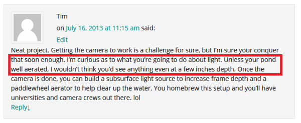
To get our 24×7 PONDCAM we need a light. We learned a lot about power consumption lately and we need a light that doesn’t’ consume that much power. Well… I do have one of these.
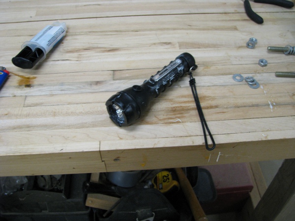
This is one of those LED flashlights that last a really long time running on batteries. My daughter uses it to read at night, but it looks a lot like just what we need. It is pretty bright. Let’s take it apart.
Note: When I found this flashlight, I thought it was the same one my daughter used. It wasn’t. I said prayers with her tonight and she asked me to fix hers because it wasn’t working right. When I am done butchering this one, I will use the leftovers to fix hers.
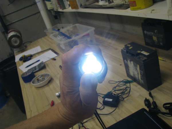
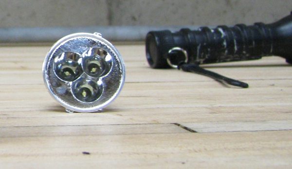
I pull the camera apart and take out the LED light assembly. Here is the part that holds those low power LEDs and produces light.
Now I have no idea if this will fit in our waterproof box or not, and I am not sure if the epoxy is dry, but I have to see if it fits. Here is what it looks like in the ugly epoxy smeared case above the camera.
They both fit. That is all I need to know for know, we can move on.
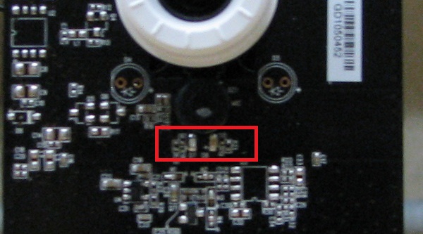
If you look closely at the front of the camera you will see the LEDs that light up when I turn on that feature in the software. This is a picture of them.
I have three options:
1) I can solder two wires on each side of the LED on there that lights up when I turn it on in software. I can attach those wires directly to the terminals on the light assembly from the flashlight. I definitely dont’ want to do this because those LEDs are so small and if I start messing with soldering there I may goof up and break the camera. Also, the circuit in the camera for that LED is meant to drive 1 LED, if I drive three it may be too much of a load and not be bright enough, or it could break whatever part of that camera drives those LEDs.
2) I can solder two wires on each side of the same LED on the camera and use it to drive a separate transistor circuit to turn on the lights. This would solve the load problem on the camera and give me nice bright lights, but I still would have to solder onto those little connectors and something could go wrong and I may break the camera. There wouldn’t be a good way to test it without turning on the camera, if I do something wrong I won’t have a chance to correct it.
3) Or I can stick a photoresistor in front of them to pick up the light from them and excite a circuit to power our lights. This would give me a completely separate circuit than the camera itself. I would be using the stock LED output to excite another circuit to turn on our lights.
I am going to option three, not only because it is the safest, but because it is the hardest of the three. Believe it or not I am going to call my 6 year old daughter to help me figure this out.
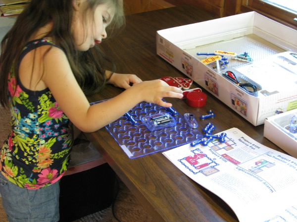
For her birthday in March I bought her “snap circuits”. They have something in that kit to help me figure out how to make a photoresistor turn on a light. Let’s take a look at what that is.
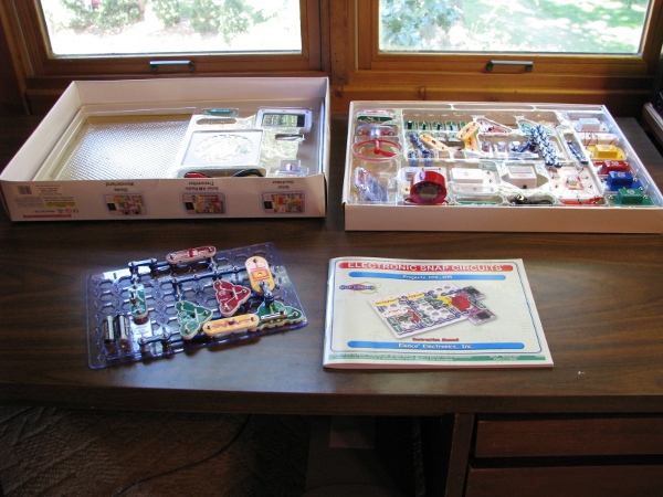
The circuit on there is the last one she did, we don’t care about that. It was some noise maker and I am a dad with little kids and I hate noise makers, I will take that all apart and have her build me this.
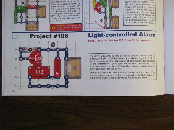
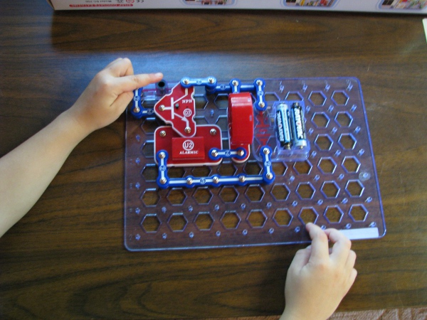
It is still a noise mater, but the description, “This alarm will sound as long as light is present”. That is what I want to know how to do, but not an alarm, but power… Power to light up our camera light.
With some help we are done with the circuit. And it looks like this.
It may be hard to see, but the idea is that if we have a little bit of current coming through the batteries on the left side of that big red triangular transistor terminal, it lets flow a lot of current flow from the top down to the alarm and then to the speaker. When she puts her finger over the photoresistor it gets quieter. We need that, but we don’t want to output sound, we want to output light. The idea is to build a circuit that when it senses light from a photoresitor, it will turn on our flashlight head we have.
I have to illustrate this circuit better because it is really important. I was in college for almost a whole year before I understood this concept. A little bit of current goes through the transistor and allows a lot of current to go through the other terminals. What you are looking at in the picture below is a “solid state switch” that is the most important thing anyone can learn from this whole project.
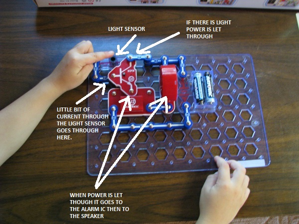
This simple circuit is what all or our technology is built on. If you see how that works you will understand why aliens don’t exist. If you don’t understand it, you will look at a digital clock and think, “Man that is a weirdo thing, aliens must have landed on the earth to teach us how to build that”.
I solder on a resistor and some wire to our light. I am worried about overloading the transistor or the lights at this point, so I stick one of our 100 ohm resistors in there. I also am sure to solder them really well, I don’t want them coming apart after we put this thing in the case.
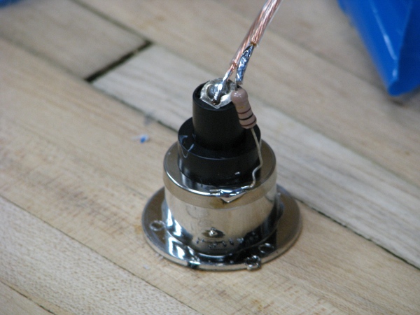
I quickly throw this together with a transistor from my component bin and we have a prototype of what we want to stick in our camera.
I stick my finger over the photoresistor and the light goes off.
I stick a quick ampmeter on this puppy to see what it draws in current.
Now that is really neat, at a cost of roughly 30 milliamps we can add a light to our camera. We are definitely doing this. But there is still a problem with both circuits. You don’t notice from the pictures, but as the light increases the light slowly lights up. If I put my hand a few inches above the photoresitor it will dim the light. My daughters alarm circuit was the same. I don’t want this. If there is any light, I want all current available to dump past the transistor and go to the light. If there isn’t any or very little light, I want no current to go to the light. I will have to think about this problem some more.
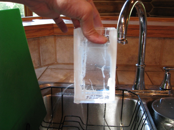
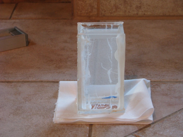
Crap I spent way too much time on that. It is too late… I have to go to Mass when I wake up. One thing before I stop is the waterproof case is dry. I filled that up with water a while ago and left it on my counter. Here is a quick picture of it.
OK, It is morning now and I have an hour or so before everyone wakes up. I really should end this post because it is getting too long. Here is a summary of where we are right now:
1) Power is still a little up in the air. I really liked it that I was able to prove the batteries we were using weren’t any good. That really should have been one of the easier parts of this project as it all of the measurements we took and even the “out of the box” requirements of everything is really low power. We will slay the power dragon yet. I do need a better way to test those batteries.
2) Connectivity: Our connectivity won’t be an issue for testing because I did move that wireless access point into the garage and put it on the window. I don’t want to leave it there, or if I do I need it to be more permanent. Right now cables are all over the floor.
3) Waterproofing: Our case, although ugly is coming along OK. I was really happy that our “late in the game” light idea will fit into the case that I measured and cut more than a week ago. It is sitting on the counter right now and I still need to check it for leaks.
4) Pond Light for 24×7 PONDCAM: The circuit my daughter built helps me better understand what I am looking for in a transistor/photoresistor circuit to make our flashlight head assembly turn on when I turn on the light for the front of the camera in the software. I have to finish this part before I can put the camera together.
5) Oh yeah… Almost forgot, my resistor bug is drying and should be dry right now. I think I will check on that first thing next post.

Great post. Great progress. I have to be honest; I’m a nitwit when it comes to electrical components. Even with that, it is interesting to see you work through the hurdles. We are all learning with you. Onto the next…
“if you understand it you’ll know that aliens don’t exist”. So true, transistors are not obvious!
Great posts. Isn’t it Ohm’s Law, not Watt’s regarding finding the right risistor (I=V/R)?
Also, am i missing something or don’t you want the light to turn on when there is NO light?
Yes. You are right, Watt’s law is P=V*I, which I referenced at the top, not I=V/R which is Ohm’s law. The issue I am having is that I can’t find where I got it wrong in this post. They are so closely related it may seem like I am talking about one when the other may apply as well. It is probably my fault as I keep thinking of that “6 watts” measurement that came off of the back of that solar panel so I fixate on that more than anything else when thinking of it, so I am probably stating something that is confusing, but not technically wrong.
Oh… And the what you said about me wanting to turn on the camera when their is “NO Light”. This is where it is totally counterintuitive. I need to turn on that light from the software of the camera. The software of the camera has the ability to turn on the light on the face of it. I have two choices here:
1) Have the light be on when the camera LED is on.
2) Have the light be off when the camera LED is on.
These two variables have nothing to do with what time of day it is but instead what we do in software. It is WAY better to have the light come one when the LED turns on because of power. We would have to design it in a different way that would be; turn off the light in the software of the camera, then the light will come on. Plus… The vast majority of the time we will want the light to be off, so only having current going to that part of the circuit when the light is on saves us power.
Pingback: My Silly Pondcam – Part 3 – Power? | Joe's Lab