
It is really late. I worked all day and wanted at least to start another post. When I started this project I had the outline of how everything would work in my head. Once I realized I had pretty much everything I needed to pull it off, I went nuts and just started building and posting. I thought it would take 3 posts, now we are on post 6 and we are not done.
I do a lot of complicated projects for a living, but this has taken all sorts of twists and turns that I wasn’t expecting. For example, I really wanted that “resistor bug” to scare someone. It was pretty strange and scary looking. It should have grossed out someone, but when I showed it to my six year old she liked it. It looked just like a toy to her. Then I showed it to my two year old (that totally gets freaked out by any bug) and got the camera all ready to take a picture, I got this.
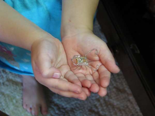
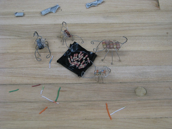
OK… Well that backfired big time. When they saw it they weren’t grossed out at all. They thought they were toys instantly and now I am building “resistor bug dads”, “resistor bug kids”, “resistor bug nests”. It is a whole production. I won’t have any resistors left when they are done (I had trouble making the resistors kids, I have to add “diodes” to my shopping list if I ever want to use one of those again).
I totally forgot where we were with this project as usual. Life has a way of having you lose your place in where you were with your amusements. So I have too look back at what we did in post 5 quick to get my bearings. OK.. I remember now… We got our waterproof case all set up. And our water resistant top too. We are on our way with that part.
Here is a picture of the waterproof case that has had water in it for a few days.
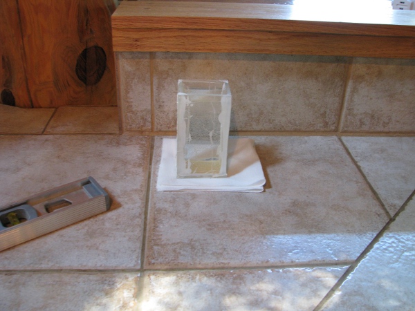
It is totally holding water. It looks OK to me.
I had a family party the other day and I showed my mom the case that I tested in water. She noticed some issues with our epoxy on the case. It looked like it was breaking down on the inside a little or at least not holding well. She didn’t want to “burst my bubble”, but when someone brings up something like that, you have to listen. If you are working on a project and you are lucky enough to have some intelligent commentary, it is better to act than to just leave it. I need to worry more about water getting into my camera housing.
The other thing we figured out, or at least it looks like we figured out is power. My gut tells me we are OK there. It just seems like that little “car-phone-charger” was too perfect. So today I want to totally focus on that light. Yes… The light… Tim has such a great idea and we need to get that working.
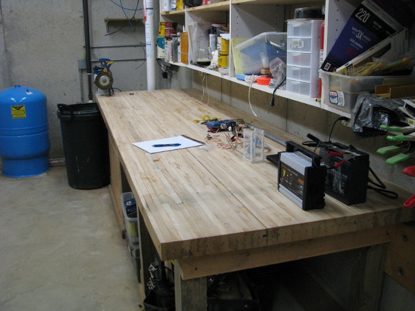
As usual there is a real lot going on so I clean everything up so I know what I have to deal with. Everything gets put away except for the things I need to work on, all tools, etc. I am left with this. A desk that is as clean as I can make it.
I will check our one “known to be good” battery fist.
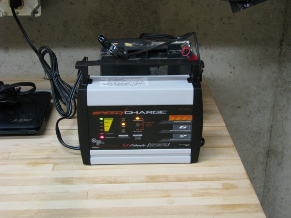
That little green light to the left means that guy has a full charge. That is good. I really want to start using the battery as much as possible because we eventually need to bring the camera out to the pond. I think the battery will be charged by the sun, but have to go it alone all dusk, night and dawn before the sun starts recharging it. We need to know more about how this guy behaves in our actual circuit. We will learn that by using it.
Another thing I want to mention about our project and power is that we really should protect our gear from overvoltage or sending too much current. To protect sensitive devices it would be best to use a fuse. I know you are thinking, “Where is he going to get a fuse for this where he doesn’t have to use math to bore the heck out of me?”. Worry not… We have one already, we got this from our 12/24 volt step down DC transformer (previously known as our “car phone battery charger”), which now is our camera’s “power supply”. Wow… Our “lingo” is all messed up for that thing. Oh well better to have more than one thing to label something than nothing at all.
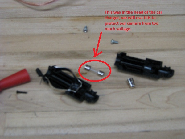
I don’t even have to learn anything about that fuse, because why? It was used in the specifications set on the package of the “car cell phone charger”. I am sure some guy with a higher degree than mine did a whole bunch of math to figure it out so I don’t have to worry. Everything about that package tells us we are safe to use it, so I don’t bother with any tests on it.
We have something to power the camera and at least we are close on the water proof (Until we really figure out a way to test it) and what I want to really focus on are all things we need to put in the water proof case. Power is figured out (I think), the connectivity is figure out (I think), the last thing is our 24×7 pondcam light. Let’s work on that.
Now when we were doing our transistor testing I really didn’t like the way those circuits were behaving. I did really like working with the transistors though because they are really neat and understanding them is crucial for understanding the entire technological universe we live in. But alas, this project is going too long so I can’t dwell on that part more. I have to find a simpler solution, one that is easy for me to explain and easier to understand. If you remember I wanted a transistor that would get a little bit of current, then just dump all the current available to the light. The transistor circuits I built didn’t do that all. I did notice that when I was looking through my component bin, the guy who organized all of the parts labeled a bag like this.
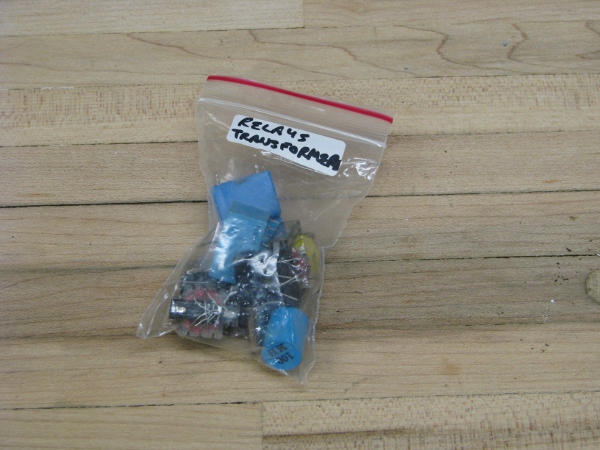
Relays and transformers? I might like to use one of those in this project. How about a relay? I will take one of those. I open the bag and pull the only one out that is in there. The principle of operation of a relay is really simple. Basically it is an electromagnet, then when turned on throws a switch. For our light, I will see if we can make the light from the LED on the face of the camera hit the photoresitor and then trip the relay which will then turn on our light.
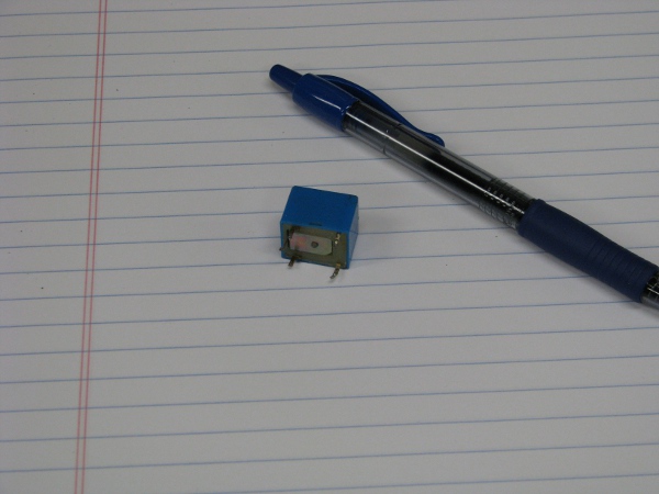
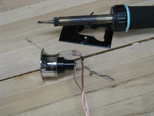
This guy is really cool. I don’t know if it works though. If I look at the pins I was either using it for something or maybe I just saw it on a board that was dead and pulled it off because it looked so neat. It is also more than 20 years old. I have to test it. That case looks like it will come off. Some relays have clear housings, not this one. Let’s take it apart.
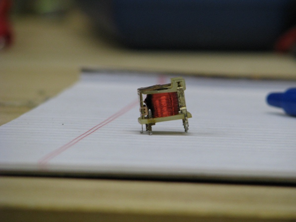
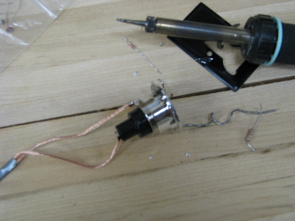
That is cool. See the electromagnet, it is just a heck of a lot of wire wrapped around a piece of metal. Then on top we have our switch. All contacts for the electromagnet and switch contacts come out the bottom. It looks pretty fragile and those wires going to the legs look really thin. I want to do some tests with it before putting the cover back on.
I grab our smallest photoresitor out of the bag, then connect some jumpers to our 5 volt power supply that came with the camera. I solder two of the legs to the resistors I chopped up making resistor-bug eggs for my kids to the legs of the relay. I then solder our photoresistor to one of these legs and connect it up to the power.
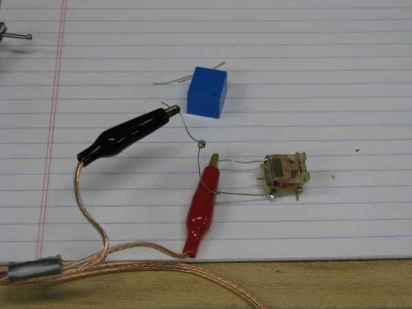
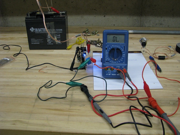
I point the photoresistor up toward the light and nothing happens. When I connect the power directly to the leads that feeds the magnet, it works, but not when the photoresistor is in there. I thought this would be a slam dunk and very easy. I grab the biggest photoreistor we have and do the same test.
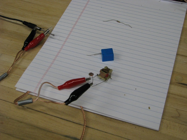
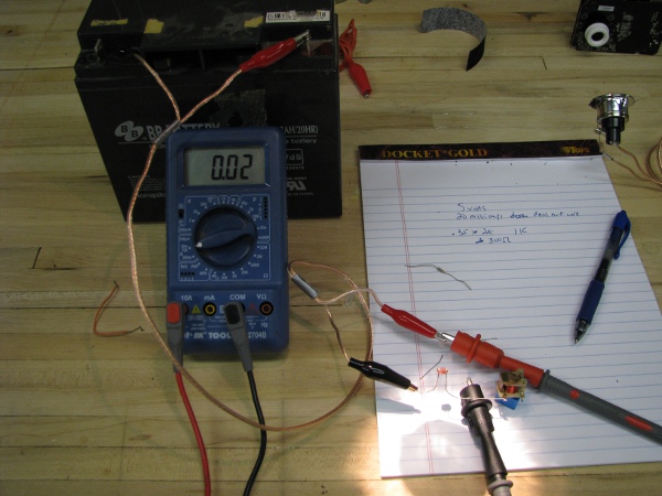
Same result, it doesn’t trip the relay unless I connect the 5 volt power supply directly to the relay. I need to see how much power is needed to make this thing go. I connect my ampmeter.
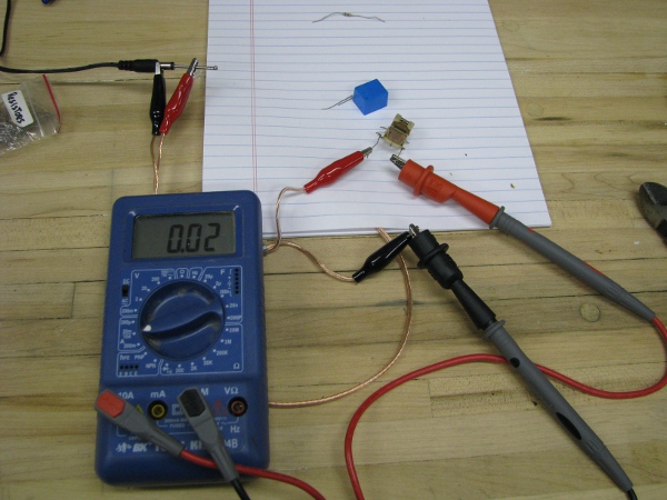
That is 20 milliamps. That isn’t that much, but guess what? We need to do a little math to understand this device better.
We have 5 volts. We need to get 20 milliamps or .02 amps to our relay. Our formula looks like this:
5 / .02 = 250
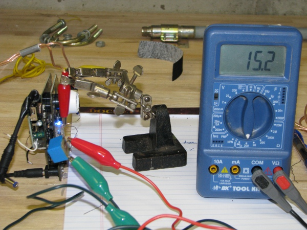
250 ohms, that seems like a photoresistor should do that. Let’s check it. I connect it up to the meter and even grab a flashlight to emulate the light on the front of the camera.
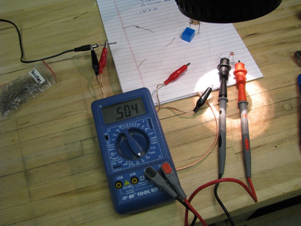
It is hard to see but the setting on the meter is at 2K. So for every “1” it would be 2000 ohms. In this case we are looking at about 1000 ohms.
It really seems like we are too far away. That is 4x the ohms we need, so to flip that relay with that photoresistor we are going to need to do something different. I was thinking about giving up and going back to solving the issue with the transistor, then I thought of something. I don’t have to use 5 volts, technically, I can drive the relay with 12 volts, but send 5 volts through to the camera light. I get our battery. I connect the circuit up just like I did with the 5 volts, but now we have 12.
I had to use the flashlight to make it work, but it did drive the relay closed.
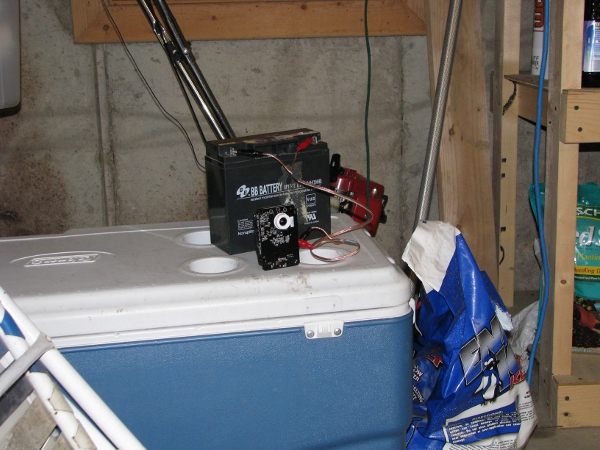
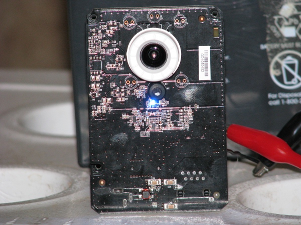
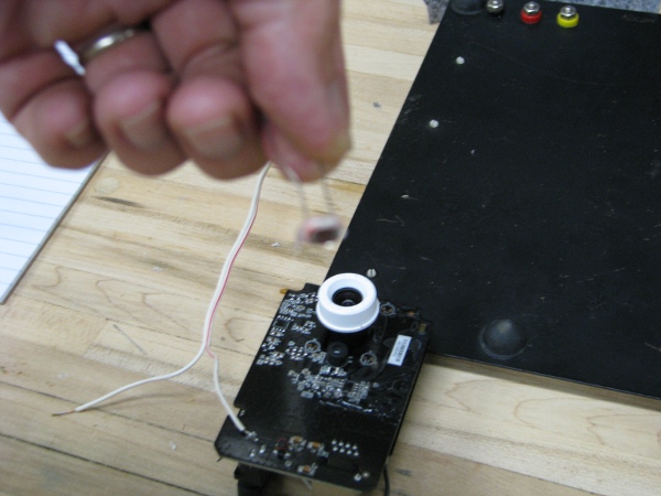
Now I have to see if our camera LED will work to drive this circuit. I can’t just connect the camera up and expect that little LED to stay on. The last several times I turned it on it was off. The easiest thing to do is bring our good battery, the camera and its little power supply out to the garage where the wireless access point has been for more than a week, connect it up and run upstairs to my office and turn the light back on. Here is what the camera looks like, plugged in and right under the wireless access point.
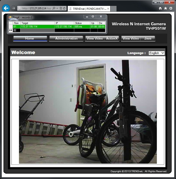
I run upstairs, ping the camera, then connect my browser to see if it is all working as expected. Yep… Looks really good.
Now I go into the software and turn on the LED.
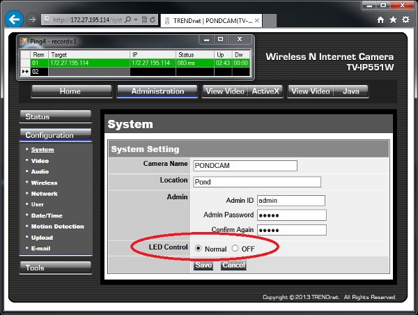
I save and run to check the camera. Yep the light is on now.
Now I have to see if I can test this. The next couple of pictures are going to be really busy, so I will try to explain them the best I can. Before I do anything neat, I have to make sure that little LED will make that relay go off with 12 volts going through our photoresistor. I do that first. I connect the ohmmeter to the relay switch part, then I connect our 12 volt battery to our photoresistor relay circuit. I am using the power supply that came with the camera so I have less to connect with jumpers.
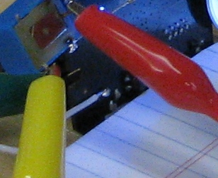
It isn’t working, I am pretty close, but can get closer. My plan in our final stage is to stick that photorestor right against that LED with some Goop glue. Here is a picture of how close it was when not working.
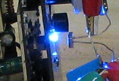
I am really messing around with this and it is hard to get it placed. Anything I move takes the photoresistor away from the camera. I continue messing around with it until I hear a “click”.
Bingo!!! That works. Now lets go nuts.
I grab our light assembly and connect it to the 5 volts and it isn’t bright enough. I remember we have that 100 ohm resistor on it. I want to cut that down, so I grab another 100 ohm resistor and piggy back it right on top of the existing one. That should give us 50 ohms and brighten things up.
I tested it and it was still not bright enough, so I pull the resistors right out all together. I want our light to be bright. At least as bright as it was running on two double A batteries in the flashlight.
Now I connect up the light to the 5 volts, and do a quick solder of an extra terminal on the 5 volt + off the front of the camera to feed into the light.
If you look at the wire at the bottom of our camera in the above picture, I sodered that while the camera and everything was connected on turned on. That is a big no no. Always power things down before soldering things. The only reason I risked it is because it was so hard to get everything right. It took so long to get it setup to the point where things were working, I didn’t dare mess with it. It saved a lot of time, just to tin that wire and pop the hot soldering iron in there for a quick connection.
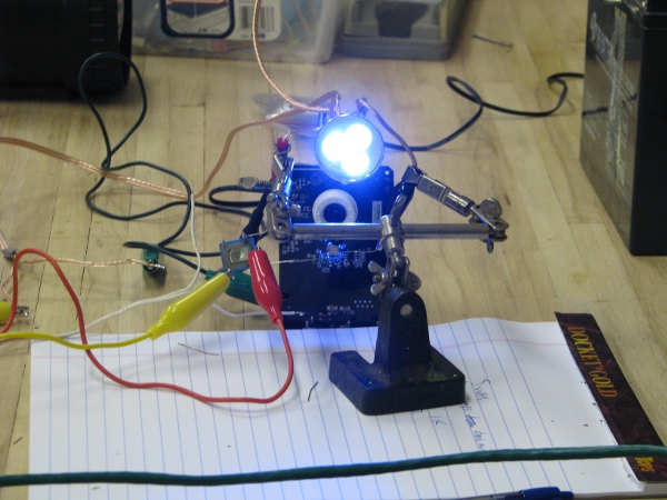
Here is everything setup and working as of right now. Our light is being turned on by our LED / photoresistor / relay concoction. The camera is running, but not connected to the wireless because it is still in the garage.
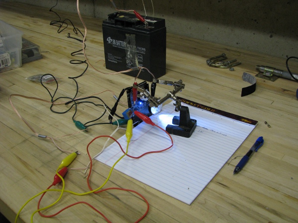
Now I know what you are thinking and I am thinking the same thing. You can test all of this because it really is all on and should work as designed. I don’t dare move this into the garage because it would take too long to set back up again. I decide I will move our access point right next to our camera. I move the light to the top which is where we will want it in our case. The green cable you see across the front is what connects the wireless access point to my network.
This looks pretty good. I turn off all lights, then run upstairs. To check things out. I connect to the camera.
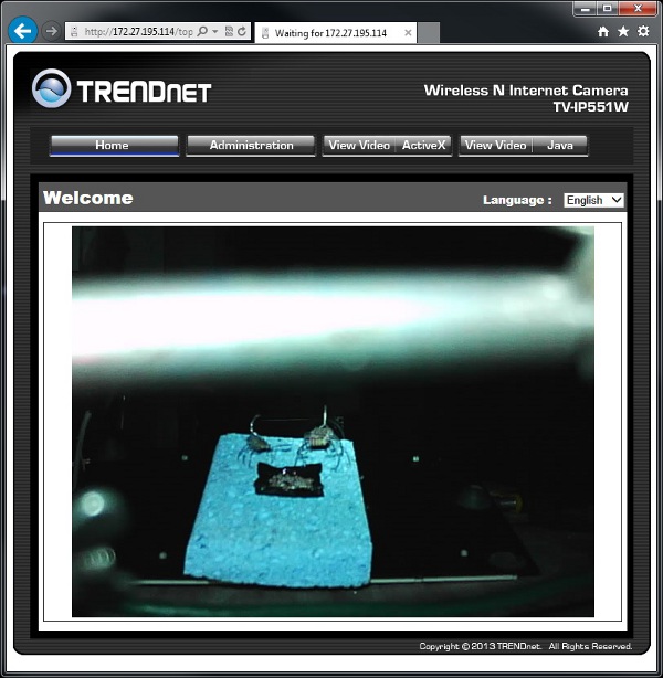
That is nice. I can see pretty OK. The resistor bugs there are about two feet from the front of the camera. They are taking care of their eggs.
I turn off the LED in the software and check the camera again.
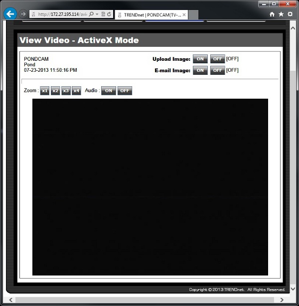
Works!
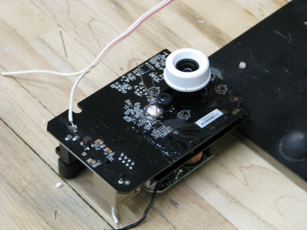
OK.. Now I have to start putting some of this together permanently. Here is what I decide to do. I am going to glue the relay next to the camera lens and then glue the photoresistor face down right on top of the power LED. Here is what it looks like as I am seeing if they will fit.
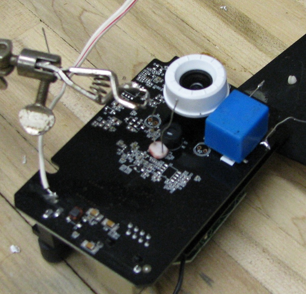
The first thing I do is smear a coating of goop to protect the camera on that right side of the lense where I want to put that relay. I don’t want any of the metal on those legs to make contact with any metal on the camera board itself. Then I put a good amount of Goop glue around the edge of the whole face of the photoresistor. I am careful not to get any of the glue on the face itself. I need that to be right against that LED if it is going to work well and have no glue in the way.
Here is how I leave it overnight. The photoresistor is mounted and there is glue smeared along the right side of the camera board to protect it from the relay.
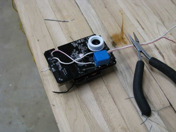
When the glue is dry I solder some of the wires to our relay / light assembly and use just a touch of glue to hold down the relay. I don’t want to just glue it down because then I will never be able to get it off if I messed something up.
While that dries I want to take advantage and look for something to do to make our next post cleaner. Oh… I see something I can do, I can put some Ethernet cable ends on that cable going through our camera case top.
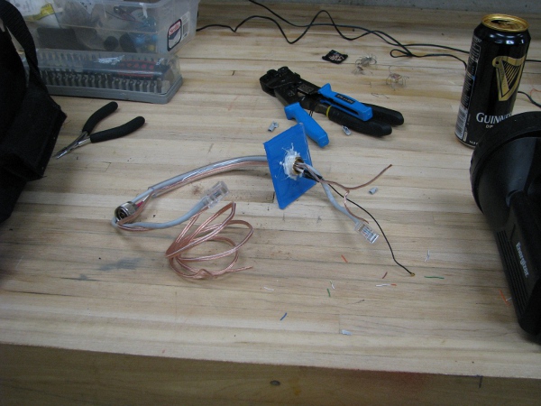
I already had my tool bag on the workbench so that was pretty easy.
Thank God for the fact that glue actually has to dry overnight. I can’t really think of anything to do right now and it is only 10:30PM. I think I will end this post in the same way I started it. Here is the resistor/diode bug family taking care of their eggs.
To continue reading see post 7.

Hi Joe,
I laughed when it turned out that you now have to make a family if “bugs”. Maybe you should sell them on Ebay!
I was thinking of your container for the camera. Instead of making a box, Why not go to target or walmart and get a nice tall plastic pitcher with a lid. I doubt there would be much distortion from the round cylinder shape. Then, all you need to do is silicone the lid down and put in a hole for the antenna.
I totally thought of something similar for the housing. I was going to use a pickle jar, but when I looked through it there was some distortion. After that I thought of the plexiglass and just stuck with it. There may be a much better way to do the waterproof housing, I just can’t figure one out.
Oh! The camera led turns the light on and off.
I’m with Charlie, I have little confidence in your container and would opt for glass tupperwear.
You guys may be totally right, but don’t you think it would be a totally good idea to figure out how to do a water proof case that is the size you want it?
I am totally afraid now of sinking this thing in water.
The whole water thing was my preoccupation in the beginning, but when we ran into those power issues, I got all distracted and kind of thought the water issues would just work out with some thought (And lots of glue).
I feel pretty good about it, but have no way to test that top without actually submerging the “waterproof camera and case”. I am a little stuck here and can’t think of a way to actually test it without submerging the camera and the case together for the test.
Pingback: My Silly Pondcam – Part 5 | Joe's Lab